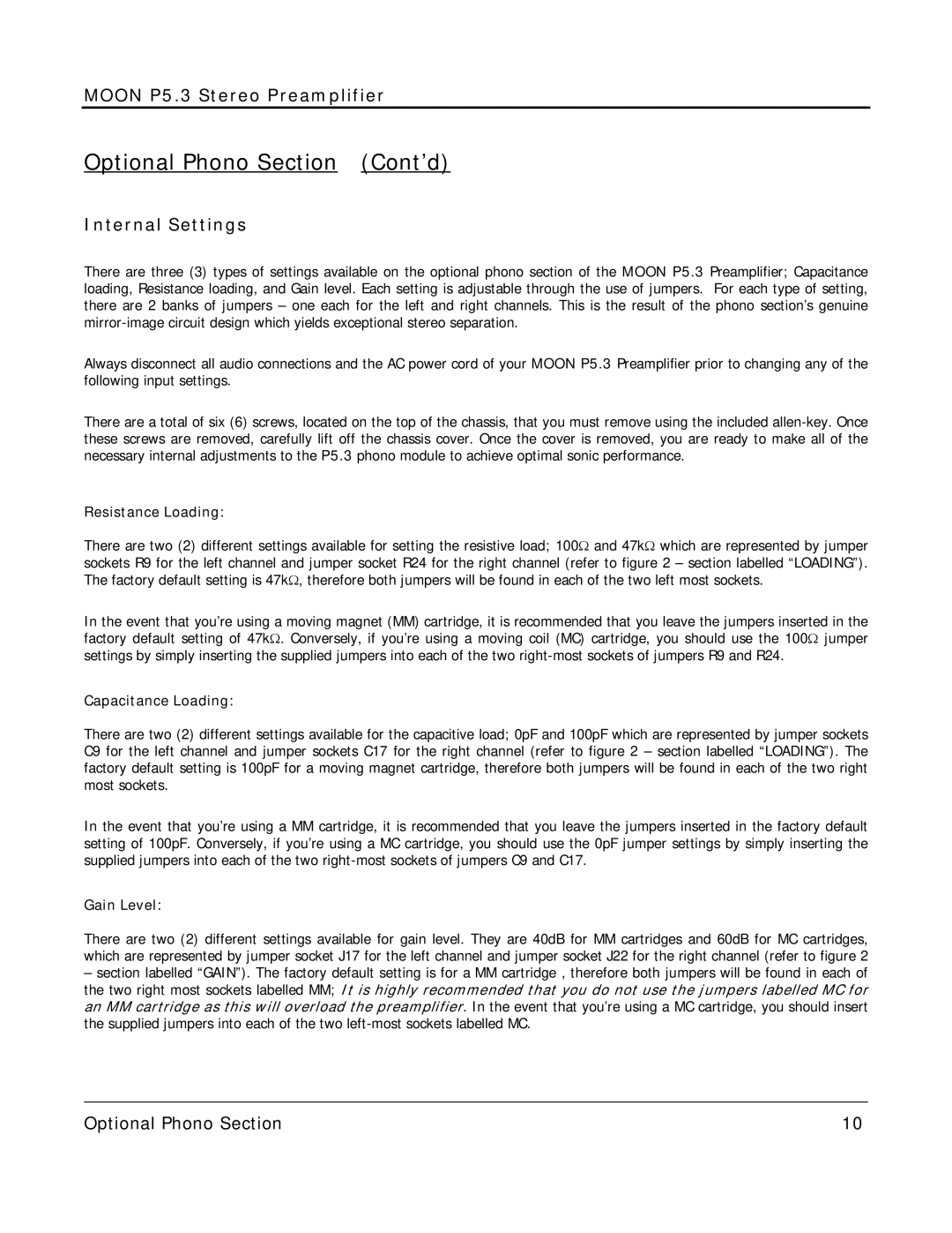
P 5.3 specifications
The Simaudio P 5.3 is a highly regarded preamplifier that showcases the company’s commitment to delivering high-fidelity audio experiences. With a sleek design and advanced engineering, this component has gained a loyal following among audiophiles and music enthusiasts alike. Simaudio, renowned for its innovative approach, has equipped the P 5.3 with a range of features that emphasize sound quality and versatility.At the heart of the P 5.3 lies its state-of-the-art analog circuitry. The preamplifier utilizes a fully balanced design that effectively minimizes noise and distortion, ensuring that the audio signal remains pure and unaltered. This design choice contributes to an expansive soundstage, allowing listeners to experience music as intended by the artist. The P 5.3 also employs Simaudio’s proprietary Moonlink technology, enabling seamless integration with other components in the Moon product line, thus creating a cohesive and high-performance audio system.
One of the standout features of the P 5.3 is its array of inputs and outputs. With multiple line-level inputs, the preamplifier offers flexibility for connecting various sources, including CD players, turntables, and digital audio players. The inclusion of a home theater bypass allows the P 5.3 to function within a multi-channel environment, making it an excellent choice for both stereo and home theater setups.
Additionally, the P 5.3 incorporates high-quality components, including premium capacitors and resistors, which further enhance its performance. The power supply is also meticulously designed to provide clean and stable energy to the circuit, thereby preventing unwanted interference that can detract from the listening experience.
The ergonomic remote control included with the P 5.3 ensures ease of use, allowing users to navigate through settings and adjust volume levels from a distance. Another significant feature is the customizable gain settings, which allow users to tailor the output level based on their specific equipment and listening preferences.
In summary, the Simaudio P 5.3 preamplifier stands out for its sophisticated design, exceptional sound quality, and user-friendly features. Its ability to blend seamlessly with other high-fidelity components, coupled with its sturdy build quality, positions it as a top choice for those seeking to enhance their audio systems. Whether for casual listening or critical evaluation, the P 5.3 delivers a remarkable listening experience that embodies the essence of high-end audio.
