A |
C |
D |
E |
B |
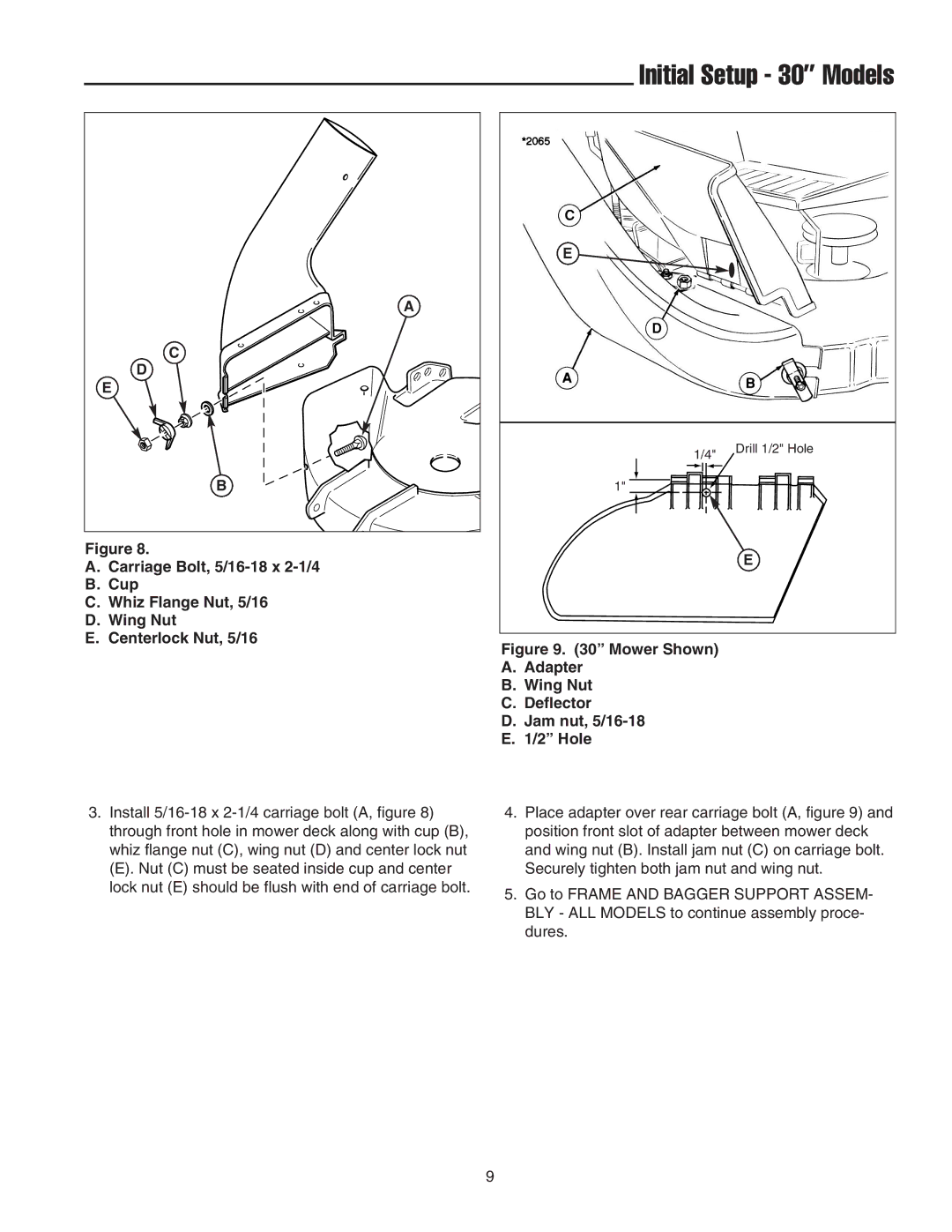
Figure 8.
A.Carriage Bolt,
B.Cup
C.Whiz Flange Nut, 5/16
D.Wing Nut
E.Centerlock Nut, 5/16
Initial Setup - 30” Models
E
1/4" Drill 1/2" Hole
1"
E
Figure 9. (30” Mower Shown)
A.Adapter
B.Wing Nut
C.Deflector
D.Jam nut, 5/16-18
E.1/2” Hole
3.Install
(E). Nut (C) must be seated inside cup and center lock nut (E) should be flush with end of carriage bolt.
4.Place adapter over rear carriage bolt (A, figure 9) and position front slot of adapter between mower deck and wing nut (B). Install jam nut (C) on carriage bolt. Securely tighten both jam nut and wing nut.
5.Go to FRAME AND BAGGER SUPPORT ASSEM- BLY - ALL MODELS to continue assembly proce- dures.
9
