Initial Setup - All Models
FRAME & BAGGER SUPPORT ASSEMBLY - ALL MODELS
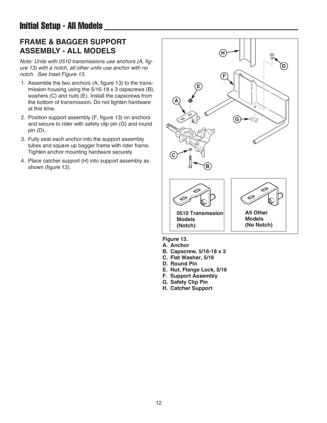
Note: Units with 0510 transmissions use anchors (A, fig- ure 13) with a notch, all other units use anchor with no notch. See Inset Figure 13.
1.Assemble the two anchors (A, figure 13) to the trans- mission housing using the
2.Position support assembly (F, figure 13) on anchors and secure to rider with safety clip pin (G) and round pin (D).
3.Fully seat each anchor into the support assembly tubes and square up bagger frame with rider frame. Tighten anchor mounting hardware securely.
4.Place catcher support (H) into support assembly as shown (figure 13).
H |
|
| D |
F |
|
E |
|
A |
|
| G |
C |
|
B |
|
0510 Transmssion | All Other |
Models | Models |
(Notch) | (No Notch) |
Figure 13.
A.Anchor
B.Capscrew,
C.Flat Washer, 5/16
D.Round Pin
E.Nut, Flange Lock, 5/16
F.Support Assembly
G.Safety Clip Pin
H.Catcher Support
12
