Service
DISCHARGE CHUTE WORM
ASSEMBLY ADJUSTMENT
If the Discharge Chute becomes difficult to rotate or begins to operate erratically, the Worm Assembly may require adjustment:
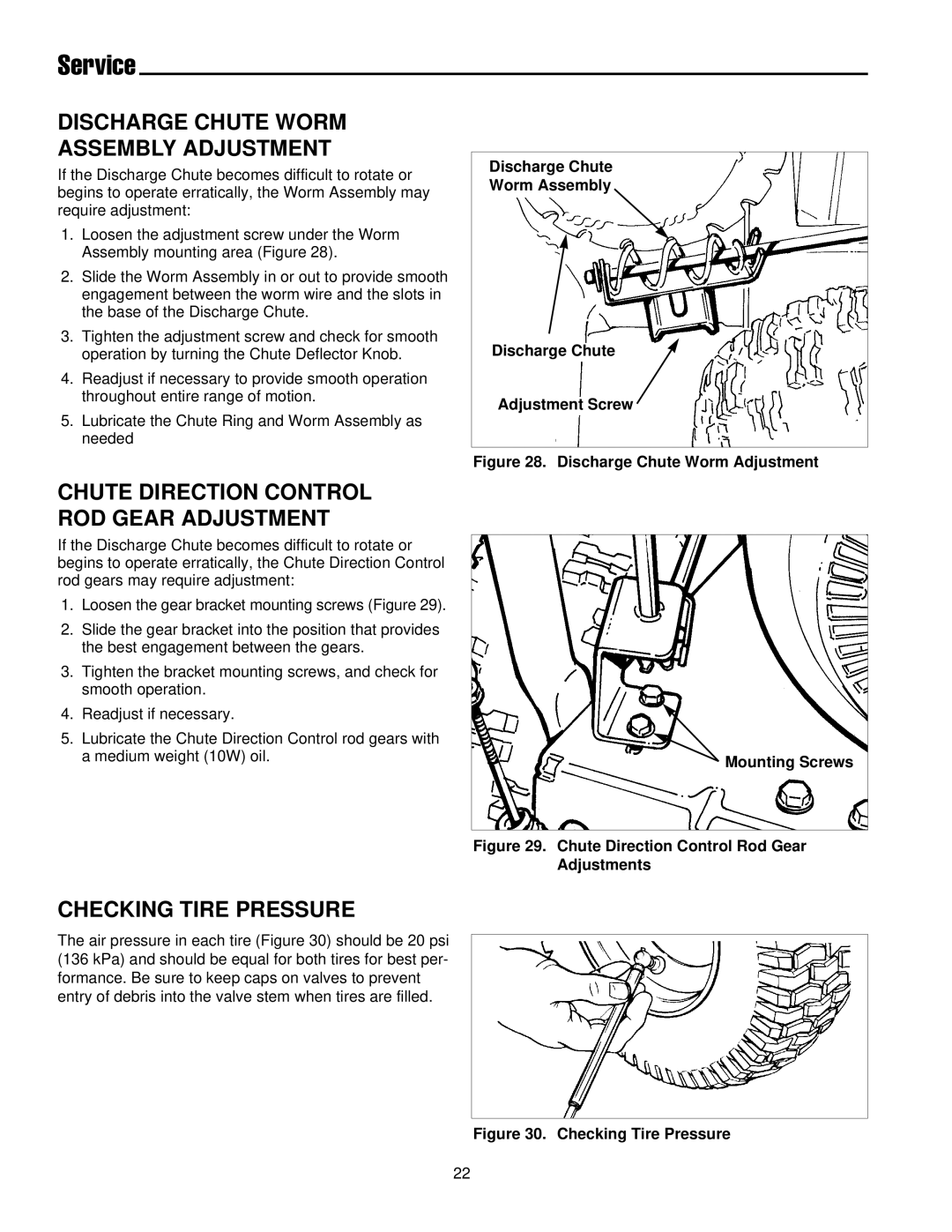
1.Loosen the adjustment screw under the Worm Assembly mounting area (Figure 28).
2.Slide the Worm Assembly in or out to provide smooth engagement between the worm wire and the slots in the base of the Discharge Chute.
3.Tighten the adjustment screw and check for smooth operation by turning the Chute Deflector Knob.
4.Readjust if necessary to provide smooth operation throughout entire range of motion.
5.Lubricate the Chute Ring and Worm Assembly as needed
Discharge Chute
Worm Assembly
Discharge Chute
Adjustment Screw
Figure 28. Discharge Chute Worm Adjustment
CHUTE DIRECTION CONTROL ROD GEAR ADJUSTMENT
If the Discharge Chute becomes difficult to rotate or begins to operate erratically, the Chute Direction Control rod gears may require adjustment:
1.Loosen the gear bracket mounting screws (Figure 29).
2.Slide the gear bracket into the position that provides the best engagement between the gears.
3.Tighten the bracket mounting screws, and check for smooth operation.
4.Readjust if necessary.
5.Lubricate the Chute Direction Control rod gears with a medium weight (10W) oil.
CHECKING TIRE PRESSURE
 Mounting Screws
Figure 29. Chute Direction Control Rod Gear Adjustments
The air pressure in each tire (Figure 30) should be 20 psi (136 kPa) and should be equal for both tires for best per- formance. Be sure to keep caps on valves to prevent entry of debris into the valve stem when tires are filled.
Figure 30. Checking Tire Pressure
22
