2000 RPM Rear PTO
Installation Instructions
Install Rear PTO Switch
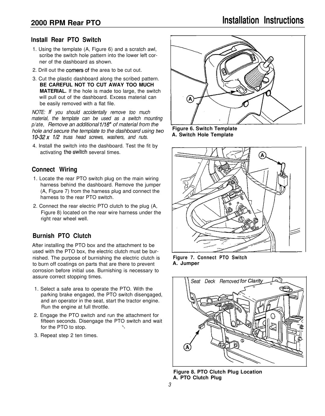
1.Using the template (A, Figure 6) and a scratch awl, scribe the switch hole pattern into the lower left cor- ner of the dashboard as shown.
2.Drill out the corners,of the area to be cut out.
3.Cut the plastic dashboard along the scribed pattern.
BE CAREFUL NOT TO CUT AWAY TOO MUCH MATERIAL. If the hole is made too large, the switch will pull out of the dashboard. Excess material can be easily removed with a flat file.
NOTE: If you should accidentally remove too much material, the template can be used as a switch mounting p/ate, Remove an additional l/16” of material from the hole and secure the template to the dashboard using two
4.Install the switch into the dashboard. Test the fit by activating the,switch several times.
Connect Wiring
1.Locate the rear PTO switch plug on the main wiring harness behind the dashboard. Remove the jumper (A, Figure 7) from the harness plug and connect the harness to the rear PTO switch.
2.Connect the rear electric PTO clutch to the plug (A, Figure 8) located on the rear wire harness under the right rear wheel well.
Figure 6. Switch Template A. Switch Hole Template
Burnish PTO Clutch
After installing the PTO box and the attachment to be used with the PTO box, the electric clutch must be bur- nished. The purpose of burnishing the electric clutch is to burn off coatings on parts that are there to prevent corrosion before initial use. Burnishing is necessary to assure correct stopping times.
1.Select a safe area to operate the PTO. With the parking brake engaged, the PTO switch disengaged, and an operator in the seat, start the tractor engine. Run the engine at full throttle.
2.Engage the PTO switch and run the attachment for fifteen seconds. Disengage the PTO switch and wait
for the PTO to stop. | ‘. |
3. Repeat step 2 ten times.
Figure 7. Connect PTO Switch A. Jumper
Seat Deck Removed
Figure 8. PTO Clutch Plug Location A. PTO Clutch Plug
3