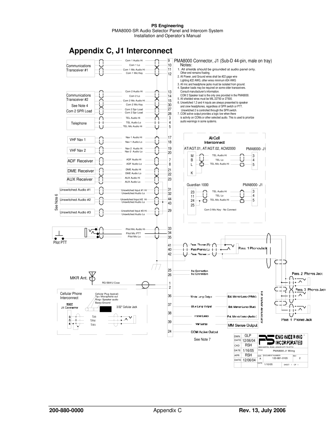
PMA8000-SR specifications
The Sirius Satellite Radio PMA8000-SR is a renowned device that integrates advanced technology with user-friendly features, making it a staple for audio enthusiasts seeking a comprehensive satellite radio experience. As part of Sirius’ expanded offerings, the PMA8000-SR provides listeners with a robust selection of channels, ensuring there's something for everyone, from music and news to sports and entertainment.One of the standout features of the PMA8000-SR is its ability to receive a vast array of satellite radio channels, offering over 150 options that cover a range of genres. This includes commercial-free music, exclusive talk shows, sports coverage, and even comedy channels. The device is designed to deliver high-quality audio, ensuring that listeners enjoy crystal-clear sound, free from the distortions often associated with traditional radio.
The PMA8000-SR incorporates digital signal processing technology which enhances audio clarity and ensures stable reception. With a user-friendly interface, the device allows users to easily navigate between channels and access key functions with minimal effort. The large display screen provides essential information at a glance, including channel names, song titles, and artists.
For in-car use, the PMA8000-SR features seamless integration with vehicles equipped for satellite radio, allowing for an uncomplicated installation process. The device supports multiple installation options, catering to various audio systems with both wired and wireless capabilities. The versatility of the PMA8000-SR ensures that it can be utilized in different environments, whether you're on a long road trip or relaxing at home.
Another notable characteristic is the built-in recording feature, allowing users to capture their favorite shows and music for later enjoyment. The device also includes pause and rewind functionalities, enabling listeners to take control of their audio experience without missing a beat. Additionally, with the compatibility for advanced features such as traffic and weather information, the PMA8000-SR goes beyond traditional radio limitations, providing real-time updates that help enhance driving convenience.
Overall, the Sirius Satellite Radio PMA8000-SR stands out due to its rich feature set, enhanced audio technologies, and exceptional versatility. It’s an ideal choice for those who crave a diverse audio experience with cutting-edge functionality, ensuring that listeners remain entertained wherever they go.

