SM 1619X04086
Assembly
Disconnect battery pack ! WARNING from tool before making
any assembly, adjustments or changing accessories. Such preventive safety measures reduce the risk of starting the tool accidentally.
INSERTING BITS
Move reverse switch lever to the center “OFF” position. Remove battery pack and rotate the clutch ring to the drill bit symbol
“ ![]()
![]() ”. Rotate the chuck sleeve counter-
”. Rotate the chuck sleeve counter-
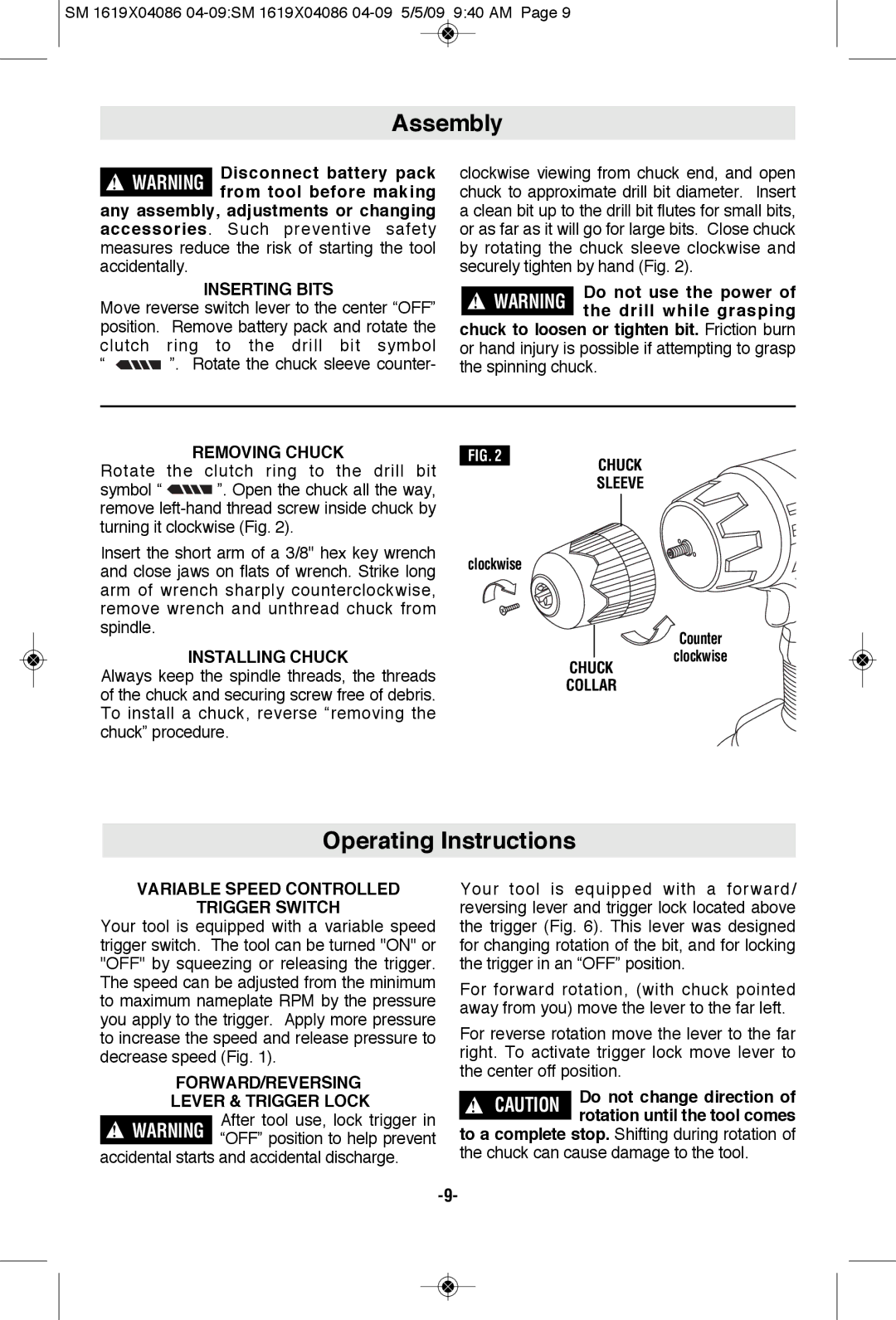
clockwise viewing from chuck end, and open chuck to approximate drill bit diameter. Insert a clean bit up to the drill bit flutes for small bits, or as far as it will go for large bits. Close chuck by rotating the chuck sleeve clockwise and securely tighten by hand (Fig. 2).
Do not use the power of ! WARNING the drill while grasping
chuck to loosen or tighten bit. Friction burn or hand injury is possible if attempting to grasp the spinning chuck.
REMOVING CHUCK
Rotate the clutch ring to the drill bit
symbol “ ![]()
![]() ”. Open the chuck all the way, remove
”. Open the chuck all the way, remove
FIG. 2
CHUCK
SLEEVE
Insert the short arm of a 3/8" hex key wrench and close jaws on flats of wrench. Strike long arm of wrench sharply counterclockwise, remove wrench and unthread chuck from spindle.
INSTALLING CHUCK
Always keep the spindle threads, the threads
clockwise
CHUCK
![]()
![]()
![]() Counter clockwise
Counter clockwise
of the chuck and securing screw free of debris. To install a chuck, reverse “re moving the chuck” procedure.
COLLAR
Operating Instructions
VARIABLE SPEED CONTROLLED
TRIGGER SWITCH
Your tool is equipped with a variable speed trigger switch. The tool can be turned "ON" or "OFF" by squeezing or releasing the trigger. The speed can be adjusted from the minimum to maximum nameplate RPM by the pressure you apply to the trigger. Apply more pressure to increase the speed and release pressure to decrease speed (Fig. 1).
FORWARD/REVERSING
LEVER & TRIGGER LOCK
After tool use, lock trigger in “OFF” position to help prevent
accidental starts and accidental discharge.
Your tool is equipped with a forward/ reversing lever and trigger lock located above the trigger (Fig. 6). This lever was designed for changing rotation of the bit, and for locking the trigger in an “OFF” position.
For forward rotation, (with chuck pointed away from you) move the lever to the far left.
For reverse rotation move the lever to the far right. To activate trigger lock move lever to the center off position.
! | CAUTION | Do not change direction of | |
rotation until the tool comes | |||
|
|
to a complete stop. Shifting during rotation of the chuck can cause damage to the tool.