Remote Control

Model 4B-101


1. INTRODUCTION


2. LEARN REMOTE CONTROL TO AAA+TM CONTROL PANEL (CONT)

The Remote Control allows you to operate the AAA+TM control panel remotely with a press of a button. You can arm the system, disarm the system and activate the alarm instantly. You also have the option to use this remote to operate other devices such as a garage door receiver.

In this package, you should find a remote control, with a 12V alkaline

ZONE

REMOTE

LED

LOCATION

Remote [6] is represented by zone LED 1

®

battery installed.

12V alkaline battery (installed)

Remote Control

1

6

2

7


3

8

4

9

5

0

Please follow the instructions below to program the remote control to the AAA+TM control panel.

2. LEARN REMOTE CONTROL TO AAA+TM CONTROL PANEL

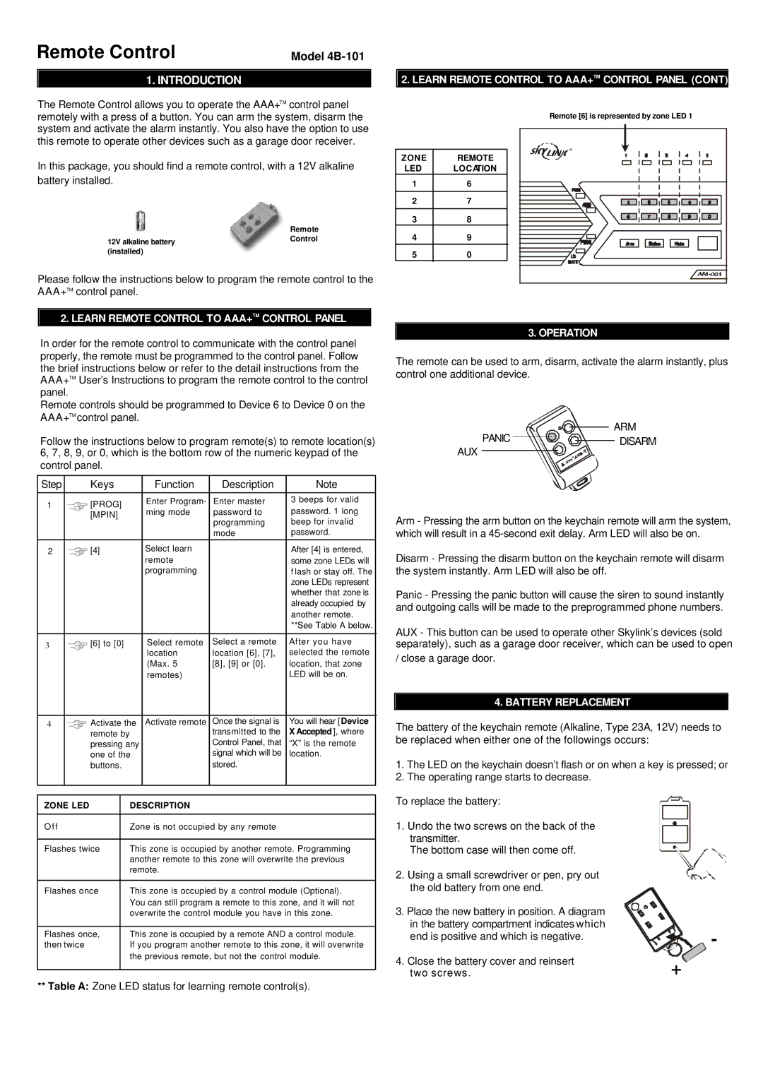
In order for the remote control to communicate with the control panel properly, the remote must be programmed to the control panel. Follow the brief instructions below or refer to the detail instructions from the AAA+TM User’s Instructions to program the remote control to the control panel.

Remote controls should be programmed to Device 6 to Device 0 on the AAA+TM control panel.

Follow the instructions below to program remote(s) to remote location(s) 6, 7, 8, 9, or 0, which is the bottom row of the numeric keypad of the control panel.

Step


Keys


Function

Description

Note


1


[PROG]


Enter Program-

Enter master

3 beeps for valid


ming mode

password to

password. 1 long


[MPIN]


programming

beep for invalid


mode

password.

2


[4]


Select learn


After [4] is entered,


remote


some zone LEDs will


programming


f lash or stay off. The


zone LEDs represent


whether that zone is


already occupied by


another remote.


**See Table A below.


3


[6] to [0]


Select remote

Select a remote

After you have


location

location [6], [7],

selected the remote


(Max. 5

[8], [9] or [0].

location, that zone


remotes)


LED will be on.


4


Activate the

Activate remote

Once the signal is

You will hear [Device


remote by


transmitted to the

X Accepted ], where


pressing any


Control Panel, that

“X” is the remote


one of the


signal which will be

location.


buttons.


stored.


ZONE LED


DESCRIPTION


O f f


Zone is not occupied by any remote


Flashes twice


This zone is occupied by another remote. Programming


another remote to this zone will overwrite the previous


remote.


Flashes once


This zone is occupied by a control module (Optional).


You can still program a remote to this zone, and it will not


overwrite the control module you have in this zone.


Flashes once,


This zone is occupied by a remote AND a control module.

then twice


If you program another remote to this zone, it will overwrite


the previous remote, but not the control module.


**Table A: Zone LED status for learning remote control(s).

3. OPERATION

The remote can be used to arm, disarm, activate the alarm instantly, plus control one additional device.

ARM

PANIC

DISARM

AUX

Arm - Pressing the arm button on the keychain remote will arm the system, which will result in a 45-second exit delay. Arm LED will also be on.

Disarm - Pressing the disarm button on the keychain remote will disarm the system instantly. Arm LED will also be off.

Panic - Pressing the panic button will cause the siren to sound instantly and outgoing calls will be made to the preprogrammed phone numbers.

AUX - This button can be used to operate other Skylink’s devices (sold separately), such as a garage door receiver, which can be used to open

/ close a garage door.

4. BATTERY REPLACEMENT

The battery of the keychain remote (Alkaline, Type 23A, 12V) needs to be replaced when either one of the followings occurs:

1.The LED on the keychain doesn’t flash or on when a key is pressed; or

2.The operating range starts to decrease.

To replace the battery:

1. Undo the two screws on the back of the transmitter.

The bottom case will then come off.

2. Using a small screwdriver or pen, pry out the old battery from one end.

3. Place the new battery in position. A diagram


in the battery compartment indicates which

-

end is positive and which is negative.


4. Close the battery cover and reinsert

+

two screws.

Page 1
Image 1
SkyLink 4B-101 manual Learn Remote Control to AAA+TM Control Panel, Operation, Battery Replacement

4B-101 specifications

SkyLink 4B-101 is an advanced telecommunications satellite designed to provide high-capacity communication services across various regions. Engineered to support a wide range of applications, including internet access, broadcasting, and emergency services, the SkyLink 4B-101 stands out in the competitive landscape of satellite technology.

One of its main features is its extensive frequency coverage. Operating in the Ku-band frequency range, the satellite can facilitate data transmission with minimal interference and significant reliability. This makes it suitable for both commercial and government applications, offering flexibility in communication pathways for diverse user needs.

The SkyLink 4B-101 is equipped with cutting-edge transponders that increase its signal processing capabilities. With multiple high-throughput transponders, it can accommodate a large number of simultaneous users, making it particularly advantageous for service providers looking to expand their reach. This enables broadband internet access in remote areas where traditional infrastructure is not feasible, bridging the digital divide.

The satellite utilizes advanced onboard processing technology, allowing it to manage bandwidth more efficiently. This technology means that users can dynamically allocate resources according to their demand. As a result, it enhances overall system performance, adapting to fluctuating user loads seamlessly and ensuring that speed and connection quality remain optimal.

Durability and resilience are paramount in the design of the SkyLink 4B-101. Built with robust materials, it can endure harsh space conditions, including extreme temperatures and radiation exposure. Its design includes redundancy systems that ensure continued operation even in the event of partial failure, enhancing its reliability as a critical communication tool.

The satellite features an array of solar panels designed for maximum energy efficiency. These solar panels harness solar energy effectively, powering the satellite’s systems while minimizing dependency on conventional energy sources. This focus on sustainability aligns with the growing demand for environmentally friendly solutions in space technology.

SkyLink 4B-101 also incorporates innovative propulsion technology, allowing for precise orbital adjustments as needed. This ensures optimal positioning for coverage over targeted regions, enhancing service quality and allowing for effective management of satellite fleets. Overall, the SkyLink 4B-101 embodies the future of satellite communication through its amalgamation of advanced technologies and features tailored for diverse communication needs.