VSPH-180, VSPH-60 specifications
Slant/Fin is a renowned name in the heating industry, renowned for its innovation, quality, and efficiency. Among its popular offerings are the VSPH-180 and VSPH-60, two highly efficient gas-fired residential boilers designed to provide reliable heating for homes.The VSPH-180 is a high-efficiency residential boiler that delivers exceptional heating performance while being mindful of energy consumption. It operates at an impressive AFUE (Annual Fuel Utilization Efficiency) rating of up to 95%, meaning it uses 95% of the fuel burned for heating, resulting in lower energy bills and reduced environmental impact. The VSPH-180 features a durable stainless steel heat exchanger that not only contributes to its efficiency but also prolongs the boiler's lifespan.
On the other hand, the VSPH-60 is a slightly smaller but equally efficient model that is perfect for apartments or smaller homes. It also boasts a remarkable AFUE rating of up to 95%, ensuring cost-effective heating solutions. The compact design of the VSPH-60 allows for easy installation in various locations, making it a versatile choice for homeowners seeking space-saving options without compromising on performance.
One of the standout technologies in both models is the modulating gas valve, which adjusts the burner’s output to match the heating demand. This feature enhances energy efficiency by preventing the boiler from working harder than necessary, ensuring consistent temperatures and reducing wear on the unit. Furthermore, both models are equipped with a built-in electronic ignition system, eliminating the need for a pilot light and adding convenience for homeowners.
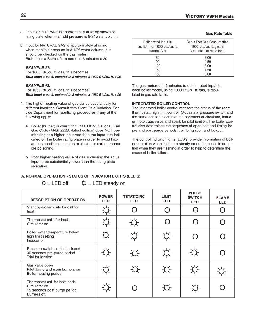
The VSPH series is designed with maintenance ease in mind. It features a user-friendly control panel that provides easy access to critical information, allowing for straightforward diagnostics and service. Regular maintenance can be performed with minimal disruption, enabling owners to keep their systems running optimally throughout the heating season.
In conclusion, the Slant/Fin VSPH-180 and VSPH-60 represent excellence in residential heating technology. With high AFUE ratings, durable construction, and advanced features, both boilers provide efficient and reliable heating solutions, ensuring comfort and energy savings for homeowners.

