Chapter 2 Hardware Installation
2.1 Panel Layout
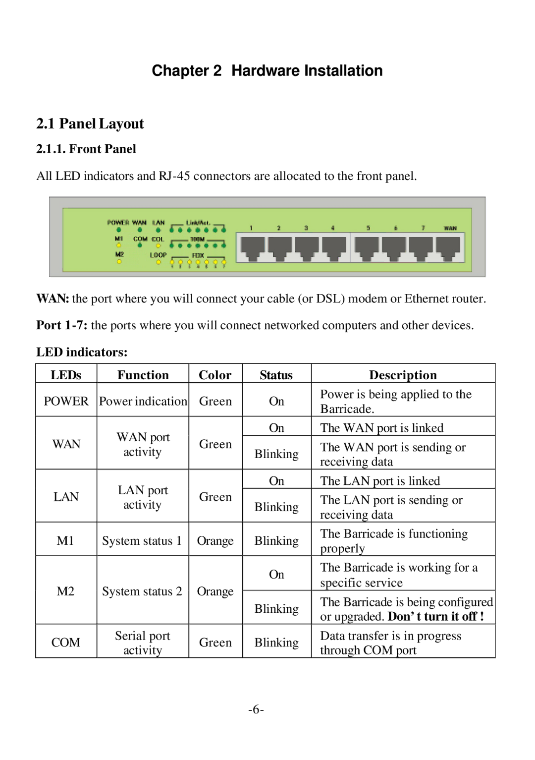
2.1.1. Front Panel
All LED indicators and
WAN: the port where you will connect your cable (or DSL) modem or Ethernet router.
Port
LED indicators:
LEDs | Function | Color | Status | Description | |
POWER | Power indication | Green | On | Power is being applied to the | |
Barricade. | |||||
|
|
|
| ||
| WAN port |
| On | The WAN port is linked | |
WAN | Green |
| The WAN port is sending or | ||
activity | Blinking | ||||
|
| receiving data | |||
|
|
|
| ||
| LAN port |
| On | The LAN port is linked | |
LAN | Green |
| The LAN port is sending or | ||
activity | Blinking | ||||
|
| receiving data | |||
|
|
|
| ||
M1 | System status 1 | Orange | Blinking | The Barricade is functioning | |
properly | |||||
|
|
|
| ||
|
|
| On | The Barricade is working for a | |
|
|
| specific service | ||
M2 | System status 2 | Orange |
| ||
Blinking | The Barricade is being configured | ||||
|
|
| |||
|
|
| or upgraded. Don’t turn it off ! | ||
|
|
|
| ||
COM | Serial port | Green | Blinking | Data transfer is in progress | |
activity | through COM port | ||||
|
|
|