Normal Removal & Installation
Normal Removal & Installation
Collector Installation
Note: See previous pages for more detailed installation and operation instructions if necessary.
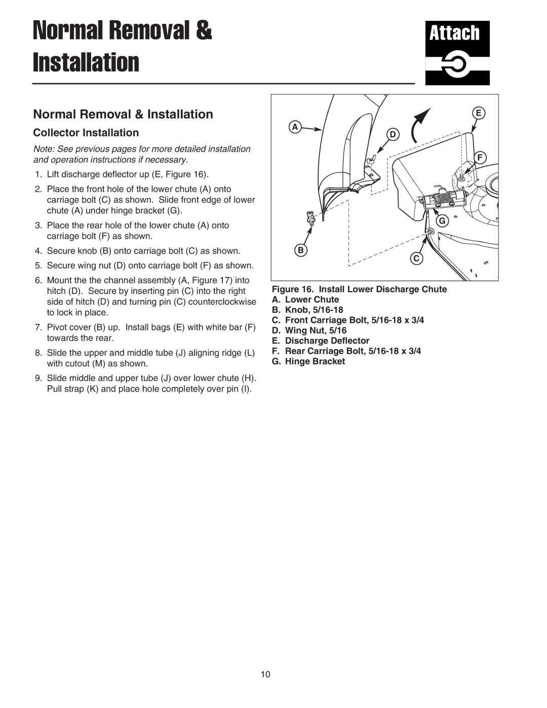
1.Lift discharge deflector up (E, Figure 16).
2.Place the front hole of the lower chute (A) onto carriage bolt (C) as shown. Slide front edge of lower chute (A) under hinge bracket (G).
3.Place the rear hole of the lower chute (A) onto carriage bolt (F) as shown.
4.Secure knob (B) onto carriage bolt (C) as shown.
5.Secure wing nut (D) onto carriage bolt (F) as shown.
6.Mount the the channel assembly (A, Figure 17) into hitch (D). Secure by inserting pin (C) into the right side of hitch (D) and turning pin (C) counterclockwise to lock in place.
7.Pivot cover (B) up. Install bags (E) with white bar (F) towards the rear.
8.Slide the upper and middle tube (J) aligning ridge (L) with cutout (M) as shown.
9.Slide middle and upper tube (J) over lower chute (H). Pull strap (K) and place hole completely over pin (I).
E |
A |
D |
F |
G |
B |
C |
Figure 16. Install Lower Discharge Chute
A.Lower Chute
B.Knob, 5/16-18
C.Front Carriage Bolt, 5/16-18 x 3/4
D.Wing Nut, 5/16
E.Discharge Deflector
F.Rear Carriage Bolt, 5/16-18 x 3/4
G.Hinge Bracket
10