| C |
|
| E | C |
|
| |
|
| G |
F |
| C |
D |
|
|
D |
|
|
D |
|
|
|
| F |
|
| B |
|
| A |
|
| D |
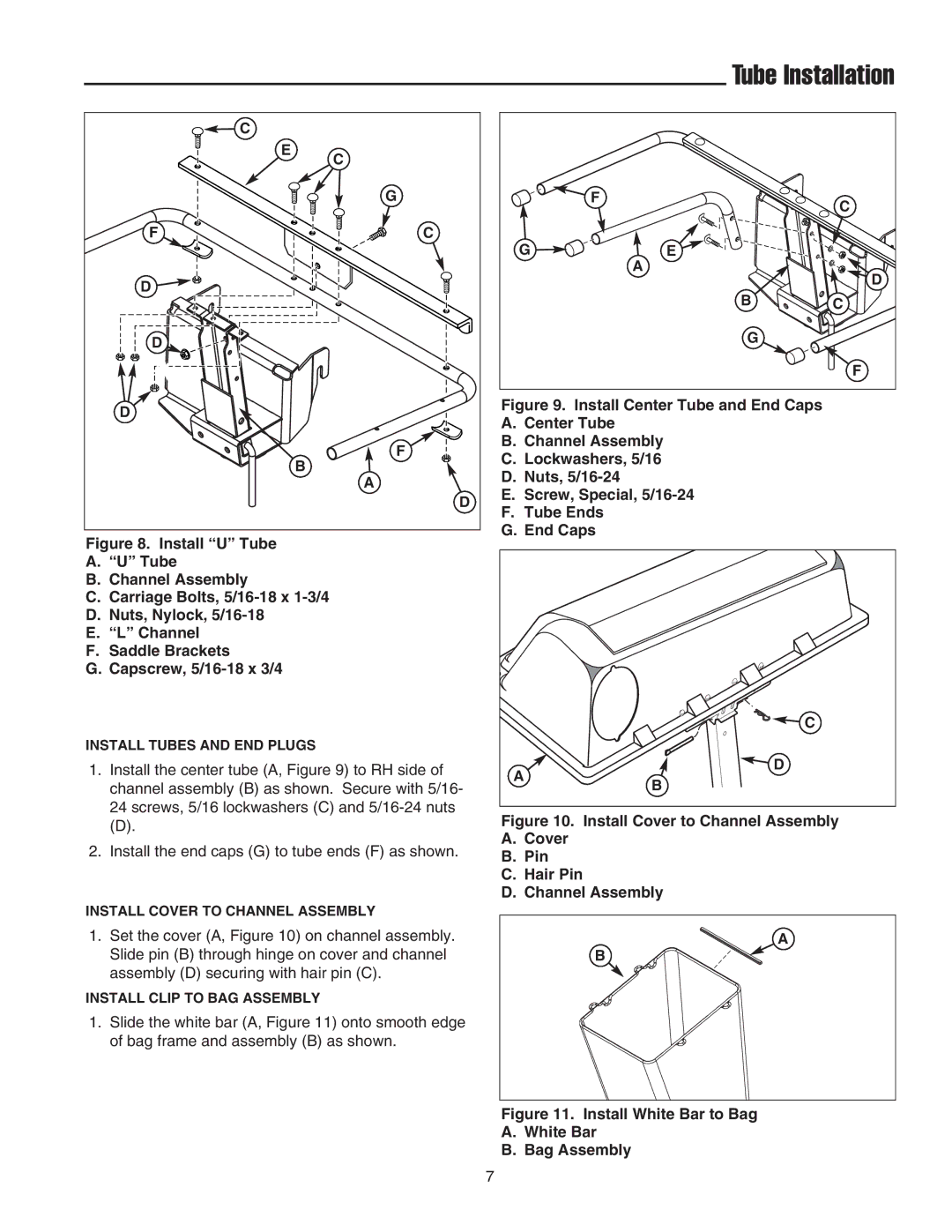
Figure 8. Install “U” Tube
A.“U” Tube
B.Channel Assembly
C.Carriage Bolts, 5/16-18 x 1-3/4
D.Nuts, Nylock, 5/16-18
E.“L” Channel
F.Saddle Brackets
G.Capscrew, 5/16-18 x 3/4
INSTALL TUBES AND END PLUGS
1.Install the center tube (A, Figure 9) to RH side of channel assembly (B) as shown. Secure with 5/16- 24 screws, 5/16 lockwashers (C) and
(D).
2.Install the end caps (G) to tube ends (F) as shown.
INSTALL COVER TO CHANNEL ASSEMBLY
1.Set the cover (A, Figure 10) on channel assembly. Slide pin (B) through hinge on cover and channel assembly (D) securing with hair pin (C).
INSTALL CLIP TO BAG ASSEMBLY
1.Slide the white bar (A, Figure 11) onto smooth edge of bag frame and assembly (B) as shown.
Tube Installation
| F | C |
|
| |
G | E |
|
| A | D |
|
| |
| B | C |
| G |
|
|
| F |
Figure 9. Install Center Tube and End Caps
A.Center Tube
B.Channel Assembly
C.Lockwashers, 5/16
D.Nuts, 5/16-24
E.Screw, Special, 5/16-24
F.Tube Ends
G.End Caps
C |
D |
A |
B |
Figure 10. Install Cover to Channel Assembly
A.Cover
B.Pin
C.Hair Pin
D.Channel Assembly
A
B
Figure 11. Install White Bar to Bag
A.White Bar
B.Bag Assembly
7