Installation Instructions |
|
DOWNWARD PRESSURE LOCK PLATE - OBSOLETE
Note:The following information applies only to models produced before October of 2002. It is being included here for reference pur- poses ONLY.
MANUAL LIFT MODELS
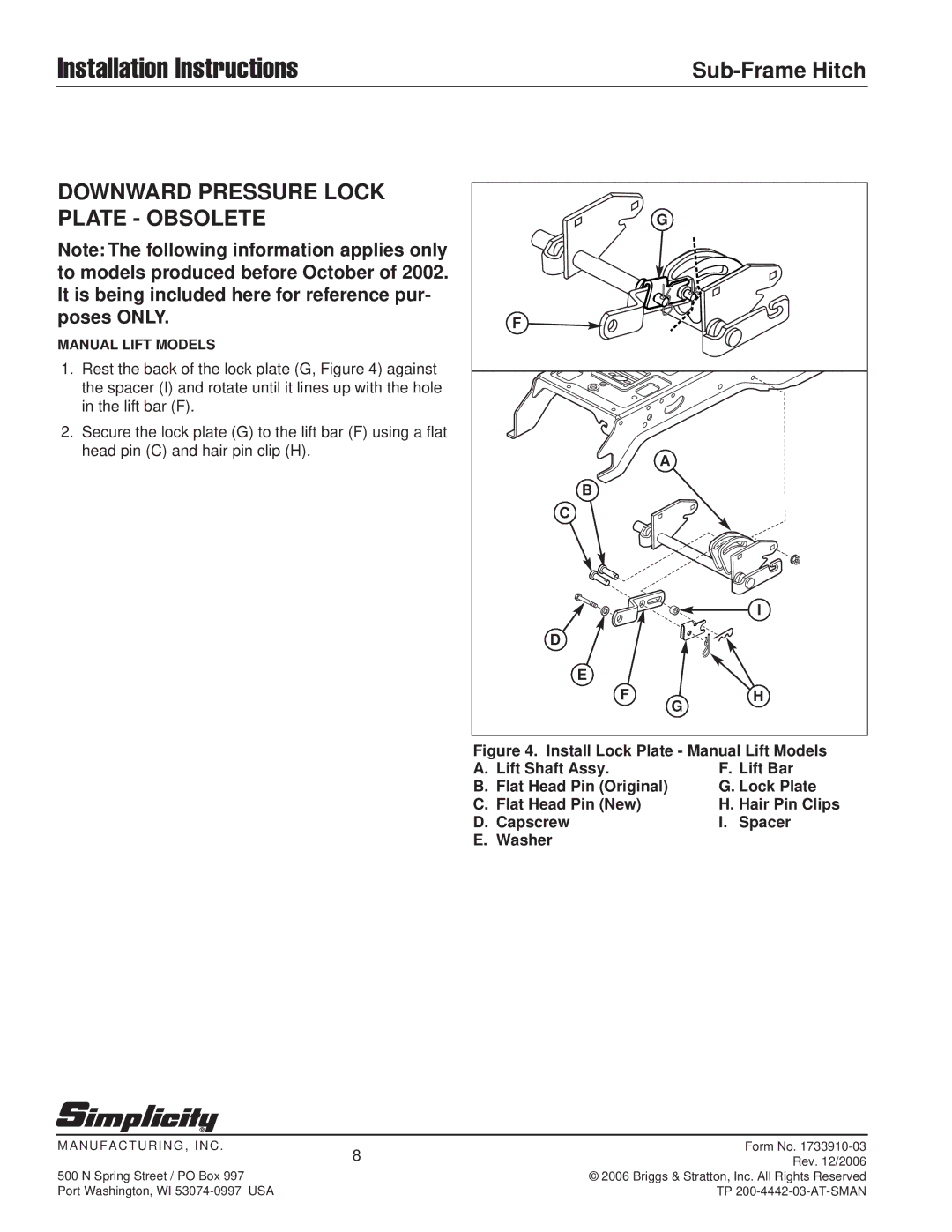
1.Rest the back of the lock plate (G, Figure 4) against the spacer (I) and rotate until it lines up with the hole in the lift bar (F).
2.Secure the lock plate (G) to the lift bar (F) using a flat head pin (C) and hair pin clip (H).
| G |
F |
|
| A |
B |
|
C |
|
| I |
D |
|
E |
|
F | H |
| G |
Figure 4. Install Lock Plate - Manual Lift Models
A. Lift Shaft Assy. | F. Lift Bar |
B. Flat Head Pin (Original) | G. Lock Plate |
C. Flat Head Pin (New) | H. Hair Pin Clips |
D. Capscrew | I. Spacer |
E. Washer |
|
MANUFACTURING, INC . | 8 | Form No. |
| Rev. 12/2006 | |
|
| |
500 N Spring Street / PO Box 997 |
| © 2006 Briggs & Stratton, Inc. All Rights Reserved |
Port Washington, WI |
| TP |