Installation Instructions |
|
| C |
A |
|
B | D |
| E |
| F |
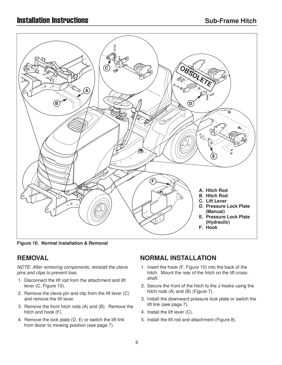
| A. Hitch Rod |
| B. Hitch Rod |
| C. Lift Lever |
| D. Pressure Lock Plate |
| (Manual) |
| E. Pressure Lock Plate |
| (Hydraulic) |
| F. Hook |
Figure 10. Normal Installation & Removal
REMOVAL | NORMAL INSTALLATION |
NOTE: After removing components, reinstall the clevis pins and clips to prevent loss.
1.Disconnect the lift rod from the attachment and lift lever (C, Figure 10).
2.Remove the clevis pin and clip from the lift lever (C) and remove the lift lever.
3.Remove the front hitch rods (A) and (B). Remove the hitch and hook (F).
4.Remove the lock plate (D, E) or switch the lift link from dozer to mowing position (see page 7).
1.Insert the hook (F, Figure 10) into the back of the hitch. Mount the rear of the hitch on the lift cross- shaft.
2.Secure the front of the hitch to the
3.Install the downward pressure lock plate or switch the lift link (see page 7).
4.Install the lift lever (C).
5.Install the lift rod and attachment (Figure 8).
6