Install Angling Control Rod
NOTE: If installing the dozer attachment on a unit equipped with a snowcab, replace the control rod sup- port (A, Figure 13) with the hanging support (Ref. No. 19, Figure 8). Mount the hanging support to the front cab
1.Set the angling control support (A, Figure 13) against the right side of the frame. Insert two
Space the lower hole away from the frame with a 5/16 washer (D). Secure using flange locknuts (E).
2.Install the eyebolt (B) in the support (A) and secure with a centerlock nut.
Initial Setup & Assembly
A
B |
C
D
E |
3.Connect the lower angling rod (F, Figure 14) to the dozer release lever using a hair pin clip and washer
(G).
4.Insert the upper control rod (C) through the eyelet (B), and secure the eyelet to the support using a 1/4- 20 centerlock nut (A).
NOTE: It may be necessary to leave the eyebolt nut (A, Figure 14) loose to prevent binding.
5.Secure the upper rod (C) to the lower rod (F) using two
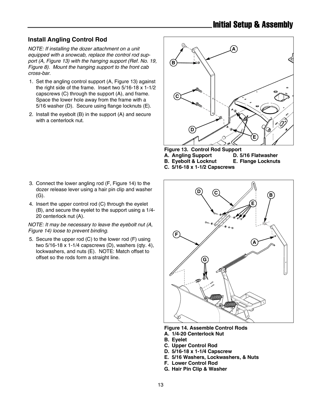
Figure 13. Control Rod Support
A. | Angling Support | D. 5/16 Flatwasher |
B. | Eyebolt & Locknut | E. Flange Locknuts |
C. 5/16-18 x 1-1/2 Capscrews
D | C | B |
|
| |
|
| E |
F |
|
|
|
| A |
| G |
|
Figure 14. Assemble Control Rods
A.1/4-20 Centerlock Nut
B.Eyelet
C.Upper Control Rod
D.5/16-18 x 1-1/4 Capscrew
E.5/16 Washers, Lockwashers, & Nuts
F.Lower Control Rod
G.Hair Pin Clip & Washer
13