Initial Setup & Assembly
2
8
1
7
3
4
6
5
3
4 | 12 |
89
8 |
11
10
8
19 18
16
21
13
18 |
15
9
14 | 16 |
|
20
17 |
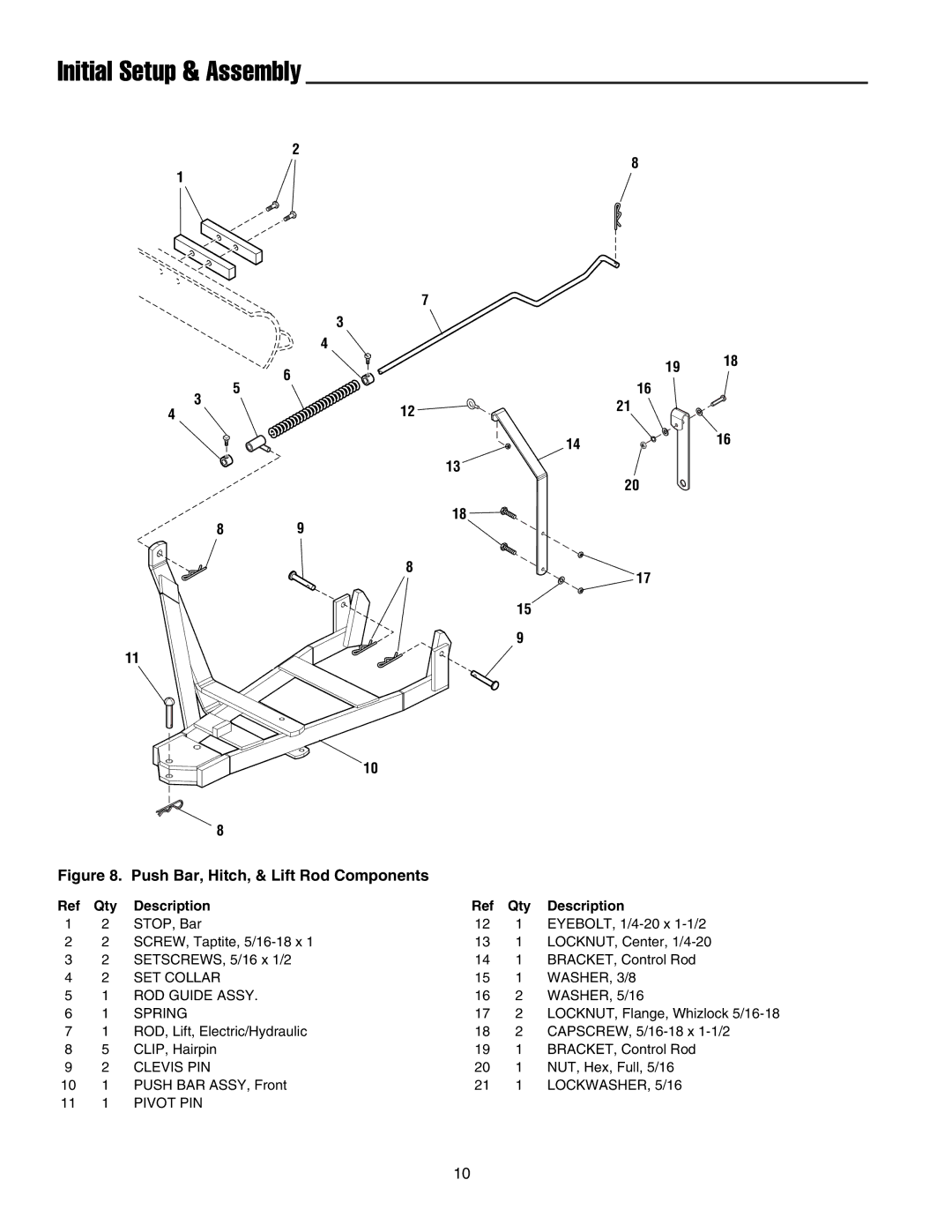
Figure 8. Push Bar, Hitch, & Lift Rod Components
Ref | Qty | Description | Ref | Qty | Description |
1 | 2 | STOP, Bar | 12 | 1 | EYEBOLT, |
2 | 2 | SCREW, Taptite, | 13 | 1 | LOCKNUT, Center, |
3 | 2 | SETSCREWS, 5/16 x 1/2 | 14 | 1 | BRACKET, Control Rod |
4 | 2 | SET COLLAR | 15 | 1 | WASHER, 3/8 |
5 | 1 | ROD GUIDE ASSY. | 16 | 2 | WASHER, 5/16 |
6 | 1 | SPRING | 17 | 2 | LOCKNUT, Flange, Whizlock |
7 | 1 | ROD, Lift, Electric/Hydraulic | 18 | 2 | CAPSCREW, |
8 | 5 | CLIP, Hairpin | 19 | 1 | BRACKET, Control Rod |
9 | 2 | CLEVIS PIN | 20 | 1 | NUT, Hex, Full, 5/16 |
10 | 1 | PUSH BAR ASSY, Front | 21 | 1 | LOCKWASHER, 5/16 |
11 | 1 | PIVOT PIN |
|
|
|
10