Initial Setup & Assembly
Assemble Lift Rod
1.Assemble lift rod per Figure 11.
Lift Rod Adjustment
Different types of terrain may require an adjustment to the lift rod assembly. For instructions on how to make this adjustment refer to the “Lift Rod Adjustment” procedure in the ADJUSTMENTS sec- tion of this manual.
D |
C |
B |
A |
Figure 11. Lift Rod Assembly
A. | Set Collars | C. Spring |
B. | Rod Guide | D. Lift Rod |
Install Blade
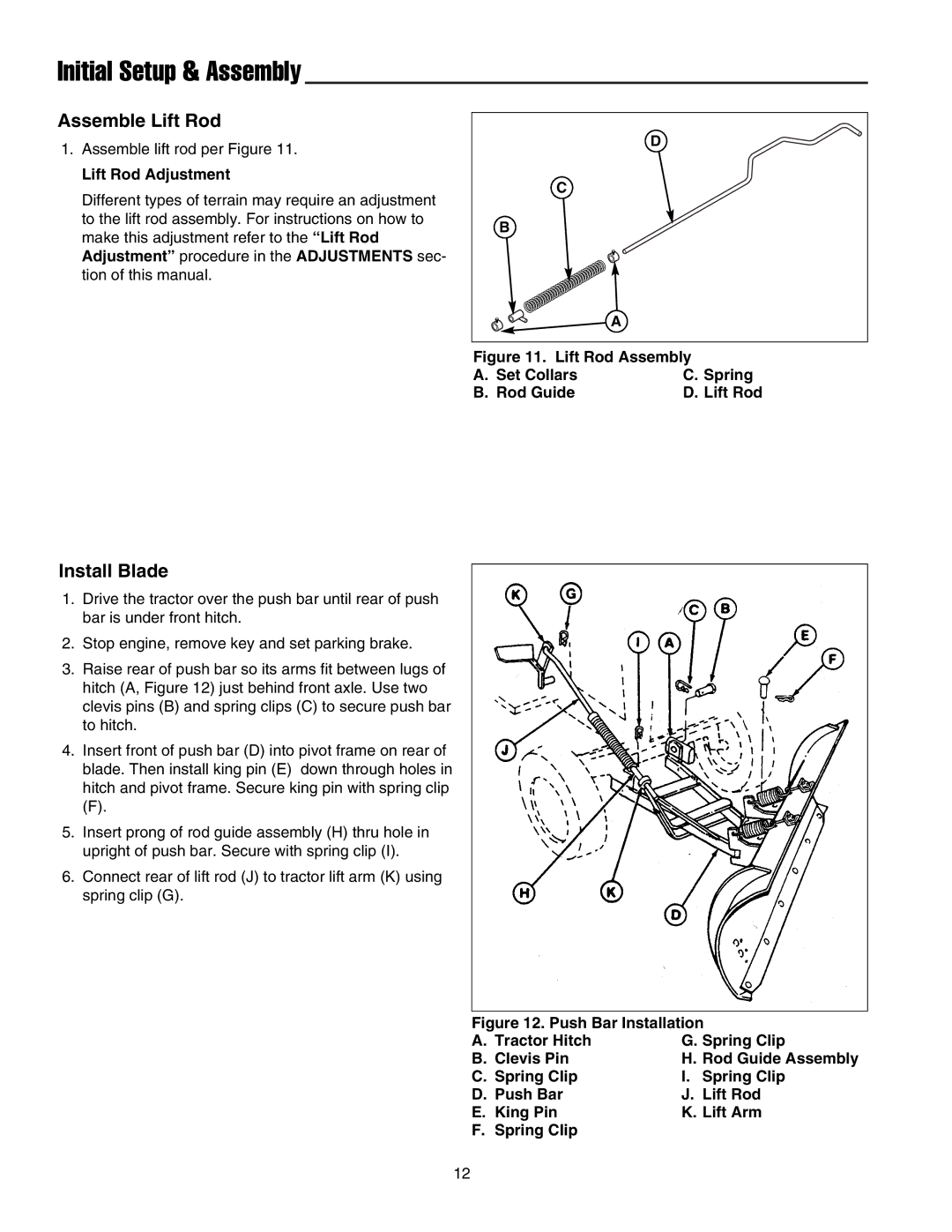
1.Drive the tractor over the push bar until rear of push bar is under front hitch.
2.Stop engine, remove key and set parking brake.
3.Raise rear of push bar so its arms fit between lugs of hitch (A, Figure 12) just behind front axle. Use two clevis pins (B) and spring clips (C) to secure push bar to hitch.
4.Insert front of push bar (D) into pivot frame on rear of blade. Then install king pin (E) down through holes in hitch and pivot frame. Secure king pin with spring clip
(F).
5.Insert prong of rod guide assembly (H) thru hole in upright of push bar. Secure with spring clip (I).
6.Connect rear of lift rod (J) to tractor lift arm (K) using spring clip (G).
Figure 12. Push Bar Installation
A. Tractor Hitch | G. Spring Clip |
B. Clevis Pin | H. Rod Guide Assembly |
C. Spring Clip | I. Spring Clip |
D. Push Bar | J. Lift Rod |
E. King Pin | K. Lift Arm |
F. Spring Clip |
|
12