Section 4 - ADJUSTMENTS & REPAIR
WARNING
DO NOT attempt any adjustments, maintenance, service or repairs with the engine running. STOP engine. STOP blade. Engage parking brake. Remove key. Remove spark plug wire from spark plug and secure away from plug. Engine and components are HOT. Avoid serious burns, allow all parts to cool before working on machine. Fuel Filler Cap and vent must be closed securely to prevent fuel spillage.
4.2MOWER DECK & COMPONENT ADJUSTMENTS 4.2.5. MOWER DECK ADJUSTMENT
(Front to Rear Levelness)
Before making deck leveling adjustments, check the tire pressure. Front tires 12 psi, rear tires 12 psi. If tires are properly inflated and mowing is still uneven, adjust
1.Remove rear hanger chains.
2.Turn each hanger pivot the same number of rotations on the
3.Reinstall rear hanger chains and measure blade tips again.
4.Repeat steps “1” through “3” until proper levelness is obtained.
REMOVE REAR HANGER
CHAINS
HAIRPIN
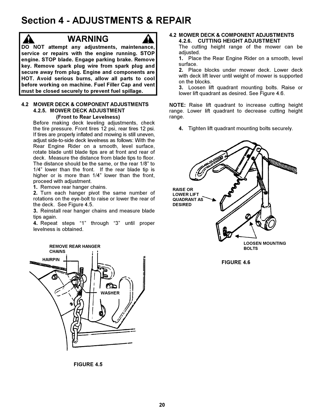
4.2MOWER DECK & COMPONENT ADJUSTMENTS 4.2.6. CUTTING HEIGHT ADJUSTMENT
The cutting height range of the mower can be adjusted.
1.Place the Rear Engine Rider on a smooth, level surface.
2.Place blocks under mower deck. Lower deck with deck lift lever until weight of mower is supported on the blocks.
3.Loosen lift quadrant mounting bolts. Raise or lower lift quadrant as desired. See Figure 4.6.
NOTE: Raise lift quadrant to increase cutting height range. Lower lift quadrant to decrease cutting height range.
4.Tighten lift quadrant mounting bolts securely.
RAISE OR
LOWER LIFT
QUADRANT AS
DESIRED
LOOSEN MOUNTING
BOLTS
FIGURE 4.6
WASHER
FIGURE 4.5
20