STEP 9: Insert the bag rod (item 4, see page 6) into the upper loop of the grass catcher bag (Item 5, see page 6) and work the grass bag until completely around the bag rod. The opening should be positioned at the bag rod opening. Push the bag rod connector (item 12, see page
6)over one end of the bag rod. Push the bag rod connector onto the rod until half of the connector is over the end of the rod. Position bag/rod assembly vertically and place foot on the inside of the bottom section. Lift the upper corner of the bag/rod assembly and guide the other end of the rod into the connector. See Figure 9. Work the rod ends together until they meet. Slide grass bag/rod into frame with open mesh to the rear of mower. Secure in place with latch.
BAG ROD
CONNECTOR
FIGURE 9
STEP 10: Slip top end of grass tube into the container top. Push backward until handle end clears the end of the chute adapter. Then slide the grass tube over the adapter opening and turn grass tube until handle base end catches under the tube latch on adapter. See Figure 10.
TUBE LATCH
GRASS TUBE | ADAPTER |
FIGURE 10
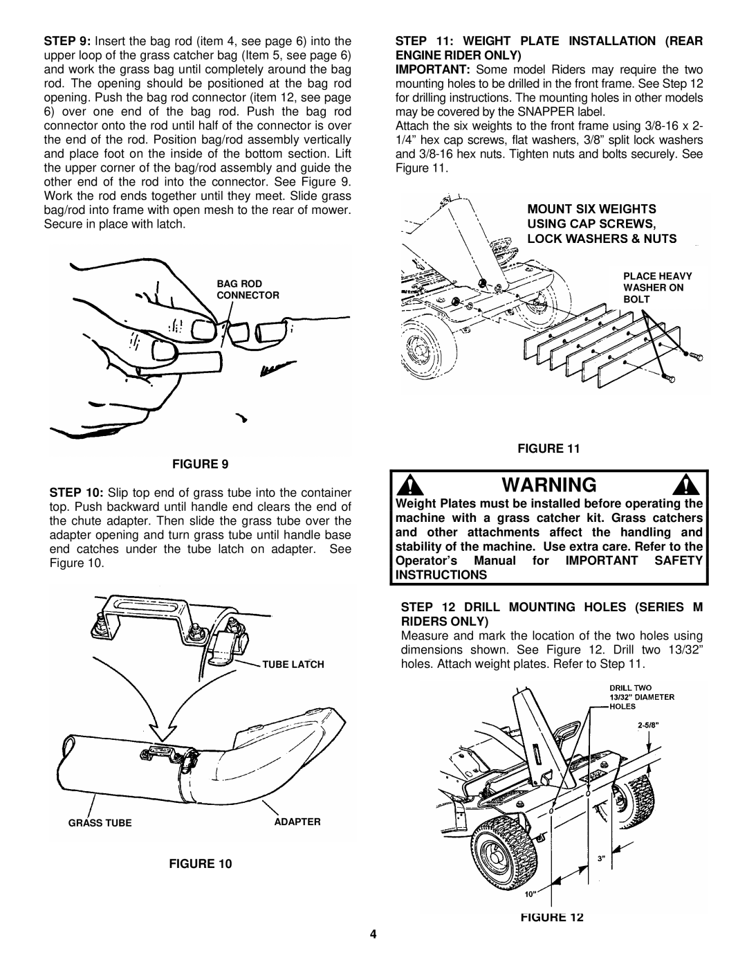
STEP 11: WEIGHT PLATE INSTALLATION (REAR ENGINE RIDER ONLY)
IMPORTANT: Some model Riders may require the two mounting holes to be drilled in the front frame. See Step 12 for drilling instructions. The mounting holes in other models may be covered by the SNAPPER label.
Attach the six weights to the front frame using
PLACE HEAVY
WASHER ON
BOLT
FIGURE 11
WARNING
Weight Plates must be installed before operating the machine with a grass catcher kit. Grass catchers and other attachments affect the handling and stability of the machine. Use extra care. Refer to the Operator’s Manual for IMPORTANT SAFETY INSTRUCTIONS
STEP 12 DRILL MOUNTING HOLES (SERIES M RIDERS ONLY)
Measure and mark the location of the two holes using dimensions shown. See Figure 12. Drill two 13/32” holes. Attach weight plates. Refer to Step 11.
FIGURE 12
4