4.With cell caps removed, connect battery charger to battery terminals; RED to positive (+) and BLACK to negative
5.If time allows, slow charge at 1 amp for 10 hours, or as an alternative, fast charge at not more than 2.5 amps for 4 hours to bring the battery to full charge. NOTE: Slow charging is recommended and extends battery life.
6.After charging, check level of electrolyte and add as needed to bring level to 3/16” above cell plates.
7.Reinstall cell caps.
WARNING
Keep sparks and flames away from battery at all times! Battery acid is corrosive. Rinse empty acid containers with water and mutilate before discarding. If acid is spilled on battery, bench, or clothing, etc., flush with clear water and neutralize with baking soda or ammonia solution.
STEP 3: BATTERY INSTALLATION
1.Carefully place the charged battery, with terminals toward front of tractor as shown on decal, in the tractor battery compartment. See Figure 1.
2.Retrieve plastic bag from under the hood, on top of gas tank. Remove nuts and bolts from plastic hardware bag.
3.Connect positive (+) cable (red) from wiring harness to the positive terminal (+) on battery using bolt and nut provided in hardware bag.
4.Connect negative
Note: Shield the positive terminal with terminal cover located on battery harness. This prevents metal from touching the positive terminal which could cause sparks.
5.Reinstall seat/pedestal assembly and tighten seat knobs securely. DO NOT operate tractor without the seat/pedestal assembly installed properly because it serves as the battery hold down.
STEP 4: STEERING WHEEL INSTALLATION
1.Place steering wheel over steering shaft located on tractor. Align hole in steering shaft with holes in steering wheel and insert roll pin. Tap roll pin with hammer gently through steering wheel and shaft until roll pin is centered on the shaft. Do not use excessive force! (See Figure 2)
FIGURE 2
Step 5: REDUCE TIRE PRESSURE
1.The tires are
STEP 6: INSTALL OPERATOR’S SEAT
Some models are shipped with the seat, hinge rod and hair pin already installed. On those models verify all seat hardware is tight and that the hair pin is inserted fully into the hinge rod and is between the hinge plate and seat pedestal. See Figure 4. All models will require the installation of the two seat cushions.
IMPORTANT: THE LOCATION OF THE HAIR PIN IN THE HINGE ROD IS CRITICAL. TO PROPERLY RETAIN THE HINGE ROD, THE HAIR PIN MUST BE BETWEEN THE HINGE PLATE AND THE SEAT PEDESTAL AND INSERTED FULLY INTO THE HINGE ROD.
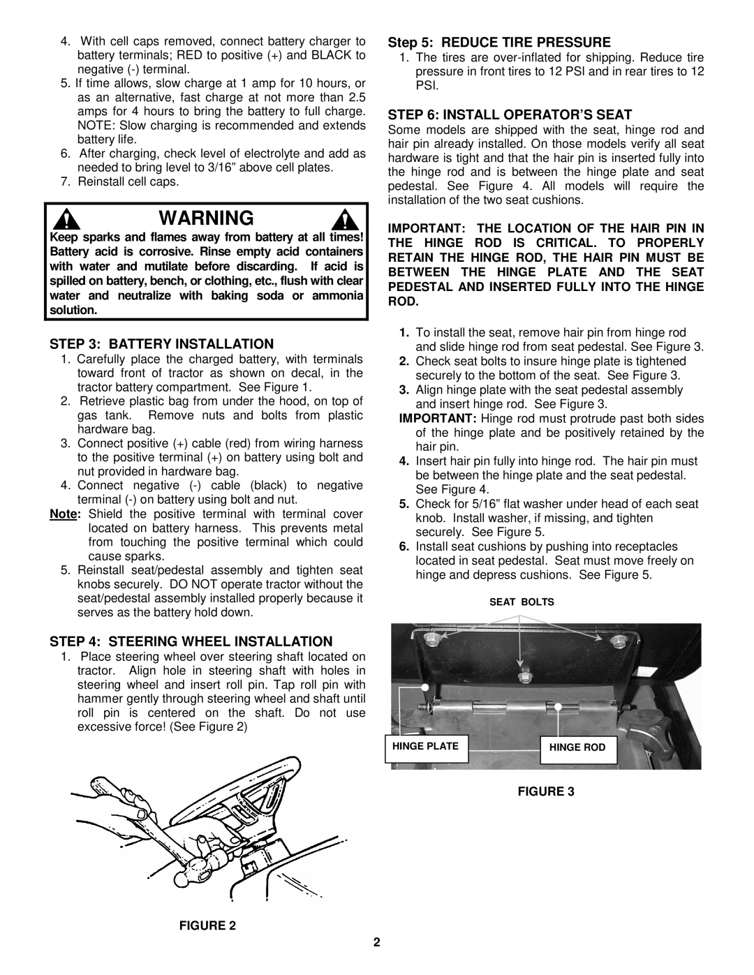
1.To install the seat, remove hair pin from hinge rod and slide hinge rod from seat pedestal. See Figure 3.
2.Check seat bolts to insure hinge plate is tightened securely to the bottom of the seat. See Figure 3.
3.Align hinge plate with the seat pedestal assembly and insert hinge rod. See Figure 3.
IMPORTANT: Hinge rod must protrude past both sides of the hinge plate and be positively retained by the hair pin.
4.Insert hair pin fully into hinge rod. The hair pin must be between the hinge plate and the seat pedestal. See Figure 4.
5.Check for 5/16” flat washer under head of each seat knob. Install washer, if missing, and tighten securely. See Figure 5.
6.Install seat cushions by pushing into receptacles located in seat pedestal. Seat must move freely on hinge and depress cushions. See Figure 5.
SEAT BOLTS
HINGE PLATE |
| HINGE ROD |
|
|
|
FIGURE 3
2