Adjustments & Service
SHEAR PIN REPLACEMENT
![]() WARNING
WARNING
Do not go near the discharge chute or auger when the engine is running. Do not run the engine with any cover or guard removed.
Under most circumstances, if the auger strikes an object which could cause damage to the unit, the shear pin will break. (This protects the gear box and other parts from damage.)
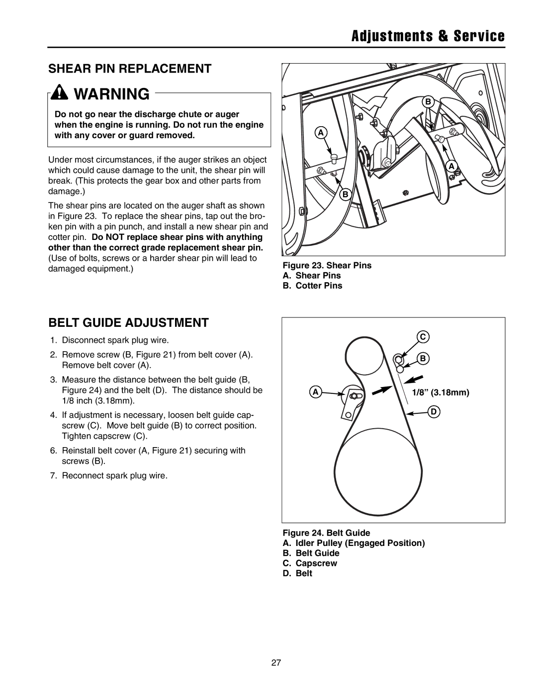
The shear pins are located on the auger shaft as shown in Figure 23. To replace the shear pins, tap out the bro- ken pin with a pin punch, and install a new shear pin and cotter pin. Do NOT replace shear pins with anything other than the correct grade replacement shear pin. (Use of bolts, screws or a harder shear pin will lead to damaged equipment.)
B |
A |
A |
B |
Figure 23. Shear Pins
A.Shear Pins
B.Cotter Pins
BELT GUIDE ADJUSTMENT
1.Disconnect spark plug wire.
2.Remove screw (B, Figure 21) from belt cover (A). Remove belt cover (A).
3.Measure the distance between the belt guide (B, Figure 24) and the belt (D). The distance should be 1/8 inch (3.18mm).
4.If adjustment is necessary, loosen belt guide cap- screw (C). Move belt guide (B) to correct position. Tighten capscrew (C).
6.Reinstall belt cover (A, Figure 21) securing with screws (B).
7.Reconnect spark plug wire.
C
B
A | 1/8” (3.18mm) |
D
Figure 24. Belt Guide
A.Idler Pulley (Engaged Position)
B.Belt Guide
C.Capscrew
D.Belt
27