Section 4 - REPAIR & ADJUSTMENTS
WARNING
Before attempting any adjustments or repairs, STOP the engine, remove the spark plug wire from the spark plug and secure wire away from plug.
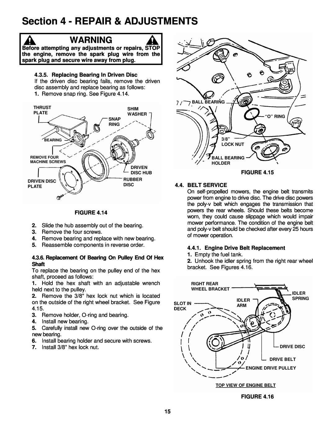
4.3.5. Replacing Bearing In Driven Disc
If the driven disc bearing fails, remove the driven disc assembly and replace bearing as follows:
1.Remove snap ring. See Figure 4.14.
THRUST | SHIM | |
PLATE | WASHER | |
| SNAP | |
| RING | |
BEARING |
| |
REMOVE FOUR |
| |
MACHINE SCREWS |
| |
| DRIVEN | |
| DISC HUB | |
DRIVEN DISC | RUBBER | |
DISC | ||
PLATE | ||
| ||
|
|
FIGURE 4.14
2.Slide the hub assembly out of the bearing.
3.Remove the four screws.
4.Remove bearing and replace with new bearing.
5.Reassemble components in reverse order.
4.3.6.Replacement Of Bearing On Pulley End Of Hex
Shaft
To replace the bearing on the pulley end of the hex shaft, proceed as follows:
BALL BEARING
“O” RING
3/8”
LOCK NUT
BALL BEARING
HOLDER
FIGURE 4.15
4.4.BELT SERVICE
On
4.4.1.Engine Drive Belt Replacement 1. Empty the fuel tank.
2. Unhook the idler spring from the right rear wheel bracket. See Figures 4.16.
1. | Hold the hex shaft with an adjustable wrench |
held next to the pulley. | |
2. | Remove the 3/8” hex lock nut which is located |
on the outside of the right wheel bracket. See Figure | |
4.15. | |
3. | Remove holder, |
4. | Install new bearing. |
5. | Carefully install new |
new bearing. | |
6. | Install bearing holder and secure with screws. |
RIGHT REAR
WHEEL BRACKET
IDLER
SLOT INARM DECK
IDLER SPRING
7. Install 3/8” hex lock nut. |
DRIVE DISC
DRIVE BELT
ENGINE DRIVE PULLEY
TOP VIEW OF ENGINE BELT
FIGURE 4.16
15