Section 4 - ADJUSTMENTS & REPAIR
WARNING
Before attempting any adjustments or repairs, STOP the engine, remove the key, remove the spark plug wire(s) from the spark plug(s) and secure wire(s) away from plug(s).
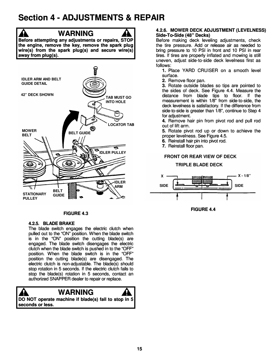
IDLER ARM AND BELT
GUIDE DETAIL
42” DECK SHOWN
TAB MUST GO INTO HOLE
LOCATOR TAB
MOWER
4.2.6. MOWER DECK ADJUSTMENT (LEVELNESS) | |
Before making deck leveling adjustments, check | |
the tire pressure. Add or release air as needed to | |
bring pressure to 10 PSI in front and 10 PSI in rear | |
tires. If tires are properly inflated and mowing is still | |
uneven, adjust | |
follows: | |
1. | Place YARD CRUISER on a smooth level |
surface. | |
2. | Remove floor pan. |
3. | Rotate outside blades so tips are pointed to |
the sides of deck. See Figure 4.4. Measure the | |
distance from blade tips to floor. If the | |
measurement is within 1/8” from | |
deck levelness is satisfactory. If the difference from | |
for adjustment. | |
4. | Remove hair pin from pivot rod and pull rod |
out of lift arm. | |
5. | Rotate pivot rod up or down to achieve the |
BELT
BELT GUIDE
IDLER PULLEY
IDLER
ARM
proper levelness. See Figure 4.5. | |
6. | Reinstall hair pin into pivot rod. |
7. | Reinstall floor pan. |
FRONT OR REAR VIEW OF DECK
TRIPLE BLADE DECK
X | X - 1/8” |
SIDE | SIDE |
BELT
STATIONARY GUIDE
PULLEY
FIGURE 4.3
4.2.5. BLADE BRAKE
The blade switch engages the electric clutch when pulled out to the “ON” position. When the blade switch is in the “ON” position the cutting blade(s) are engaged. The blade switch disengages the electric clutch when the blade switch is pushed in to the “OFF” position. When the blade switch is in the “OFF” position the cutting blade(s) are disengaged. The electric clutch is
WARNING
FIGURE 4.4
DO NOT operate machine if blade(s) fail to stop in 5 seconds or less.
15