HZS14331BVE, HZS14381BVE, HZS15421KVE, HZS15422KVE, HZS18482BVE specifications
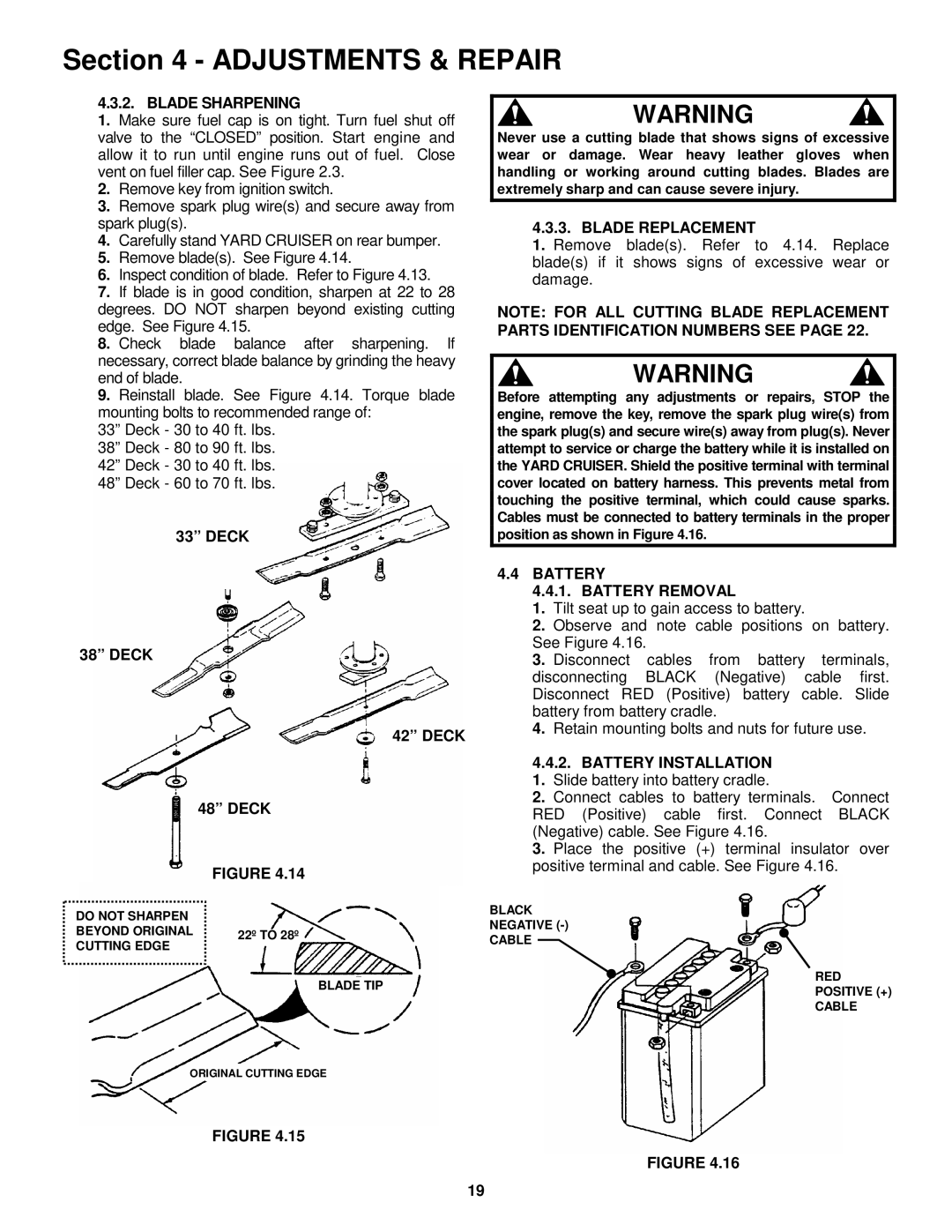
Snapper is a recognized name in the outdoor power equipment industry, and its latest series of zero-turn mowers is no exception. The Snapper HZS14331BVE, HZS14381BVE, HZS15421KVE, HZS15422KVE, and HZS18482BVE models bring a host of powerful features, cutting-edge technologies, and user-friendly characteristics to enhance lawn care efficiency.The HZS14331BVE model is equipped with a reliable 14.5 HP engine, offering a balance of power and fuel efficiency, making it excellent for homeowners with average-sized lawns. Its compact design enhances maneuverability, allowing users to navigate tight spaces with ease. The machine is built with a durable steel frame, ensuring longevity while providing stability on various terrains.
Following closely is the HZS14381BVE, which steps up with an 18 HP engine, providing that extra power for tackling more extensive lawns or tougher grass conditions. This model incorporates a 42-inch cutting deck, allowing for an efficient mowing experience. The deck’s design promotes optimum airflow, resulting in a cleaner cut and better grass dispersal.
The HZS15421KVE offers even more capability with a 21 HP engine. It emphasizes speed and precision, featuring a user-friendly hydrostatic transmission system that allows for easy control and a smooth driving experience. This model is particularly designed for homeowners wanting a machine that combines performance with comfort.
With the HZS15422KVE, users will see a significant upgrade in cutting width, with a robust 54-inch deck that can handle larger properties efficiently. Its comfortable seat and adjustable steering controls ensure that operators can mow for extended periods without fatigue. The model also includes a mulching option, allowing for a versatile approach to lawn care.
Finally, the HZS18482BVE boasts an impressive 24 HP engine, designed for heavy-duty performance. It is ideal for commercial use or homeowners with large properties. This mower combines efficiency with advanced features, including a high-back seat for maximum comfort and an innovative control panel that provides essential information at a glance.
Across this range, all models are characterized by excellent durability, ergonomic designs, and powerful cutting capabilities. Snapper's commitment to quality is evident in their use of high-grade materials and innovative technologies, allowing users to achieve a perfectly manicured lawn with ease and efficiency. These zero-turn mowers are not just tools; they are essential companions that enhance the mowing experience for both enthusiasts and professionals alike.

