Section 3 - ADJUSTMENTS & REPAIR
3.4 TILLER TINES
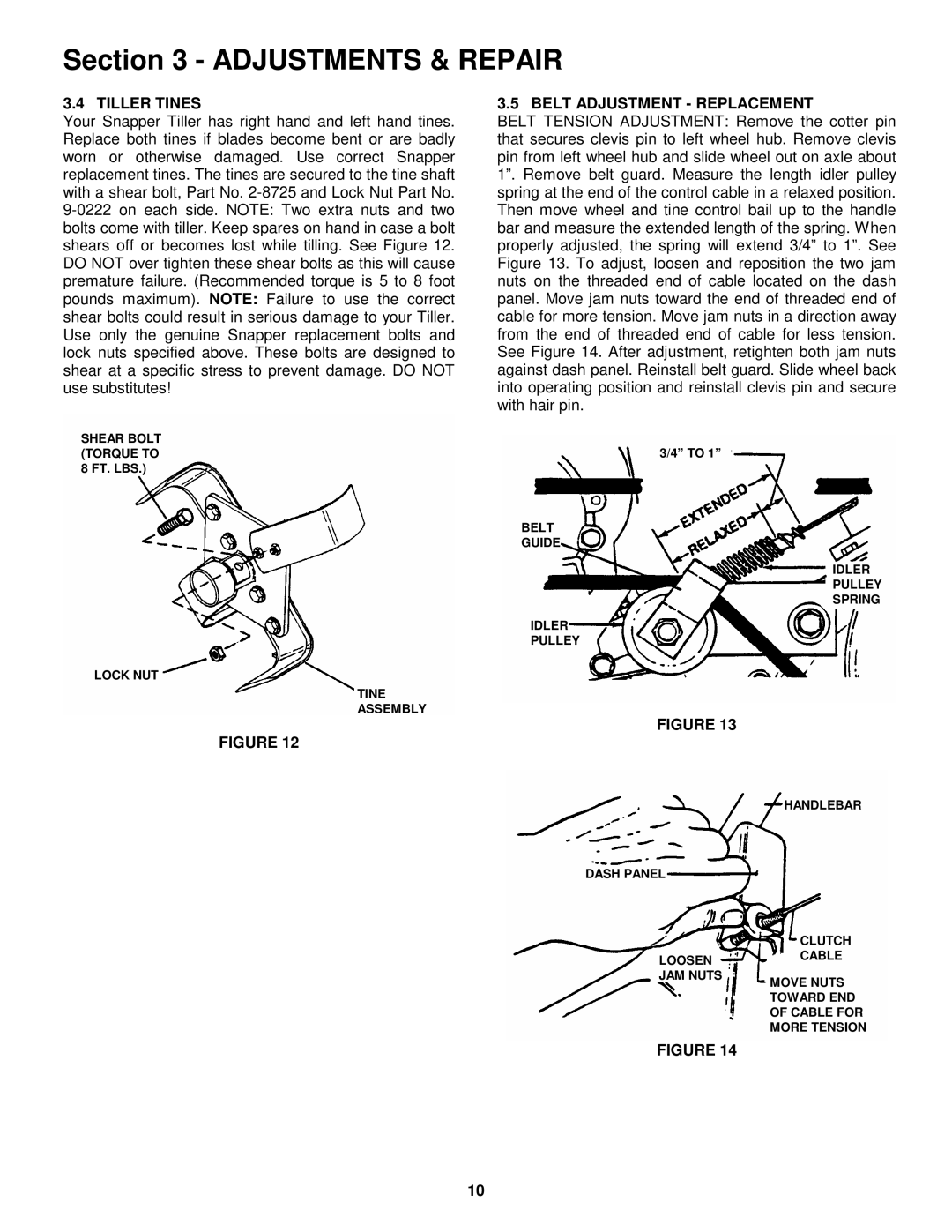
Your Snapper Tiller has right hand and left hand tines. Replace both tines if blades become bent or are badly worn or otherwise damaged. Use correct Snapper replacement tines. The tines are secured to the tine shaft with a shear bolt, Part No.
SHEAR BOLT (TORQUE TO 8 FT. LBS.)
LOCK NUT
TINE
ASSEMBLY
FIGURE 12
3.5 BELT ADJUSTMENT - REPLACEMENT
BELT TENSION ADJUSTMENT: Remove the cotter pin that secures clevis pin to left wheel hub. Remove clevis pin from left wheel hub and slide wheel out on axle about 1”. Remove belt guard. Measure the length idler pulley spring at the end of the control cable in a relaxed position. Then move wheel and tine control bail up to the handle bar and measure the extended length of the spring. When properly adjusted, the spring will extend 3/4” to 1”. See Figure 13. To adjust, loosen and reposition the two jam nuts on the threaded end of cable located on the dash panel. Move jam nuts toward the end of threaded end of cable for more tension. Move jam nuts in a direction away from the end of threaded end of cable for less tension. See Figure 14. After adjustment, retighten both jam nuts against dash panel. Reinstall belt guard. Slide wheel back into operating position and reinstall clevis pin and secure with hair pin.
3/4” TO 1”
BELT
GUIDE
IDLER
PULLEY
SPRING
IDLER
PULLEY
FIGURE 13
HANDLEBAR
DASH PANEL
LOOSEN
JAM NUTS
CLUTCH CABLE
MOVE NUTS
TOWARD END
OF CABLE FOR
MORE TENSION
FIGURE 14
10