Section 2 - OPERATING INSTRUCTIONS
2.1 BEFORE OPERATING:
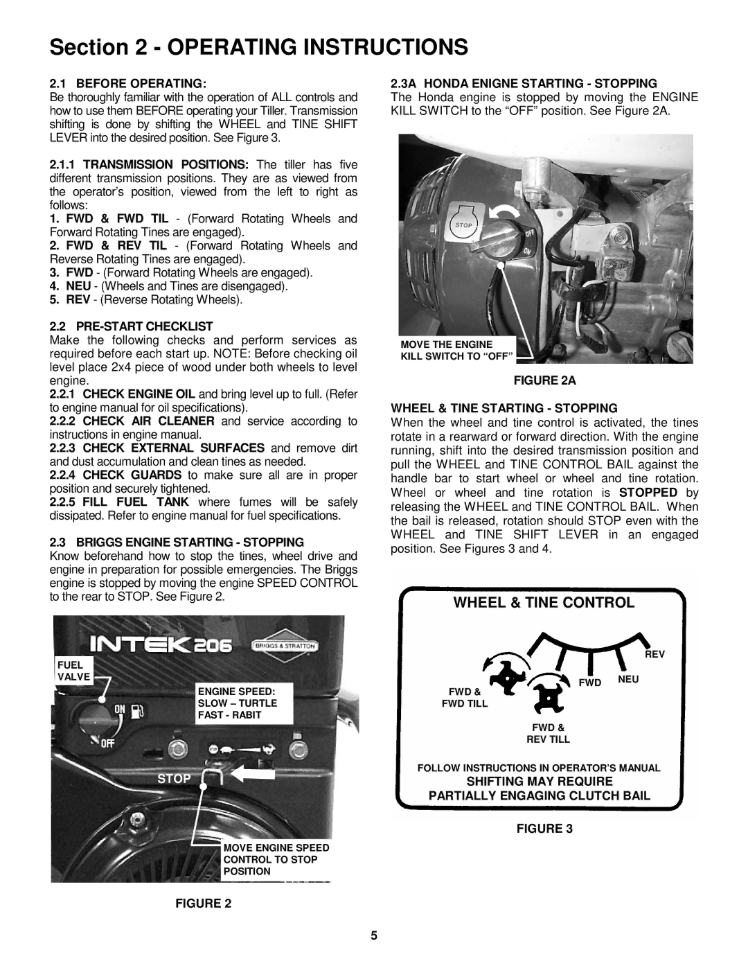
Be thoroughly familiar with the operation of ALL controls and how to use them BEFORE operating your Tiller. Transmission shifting is done by shifting the WHEEL and TINE SHIFT LEVER into the desired position. See Figure 3.
2.1.1TRANSMISSION POSITIONS: The tiller has five different transmission positions. They are as viewed from the operator’s position, viewed from the left to right as follows:
1. FWD & FWD TIL - (Forward Rotating Wheels and Forward Rotating Tines are engaged).
2. FWD & REV TIL - (Forward Rotating Wheels and Reverse Rotating Tines are engaged).
3. FWD - (Forward Rotating Wheels are engaged).
4. NEU - (Wheels and Tines are disengaged).
5. REV - (Reverse Rotating Wheels).
2.2 PRE-START CHECKLIST
Make the following checks and perform services as required before each start up. NOTE: Before checking oil level place 2x4 piece of wood under both wheels to level engine.
2.2.1CHECK ENGINE OIL and bring level up to full. (Refer to engine manual for oil specifications).
2.2.2CHECK AIR CLEANER and service according to instructions in engine manual.
2.2.3CHECK EXTERNAL SURFACES and remove dirt and dust accumulation and clean tines as needed.
2.2.4CHECK GUARDS to make sure all are in proper position and securely tightened.
2.2.5FILL FUEL TANK where fumes will be safely dissipated. Refer to engine manual for fuel specifications.
2.3 BRIGGS ENGINE STARTING - STOPPING
Know beforehand how to stop the tines, wheel drive and engine in preparation for possible emergencies. The Briggs engine is stopped by moving the engine SPEED CONTROL to the rear to STOP. See Figure 2.
FUEL
VALVE
ENGINE SPEED:
SLOW – TURTLE
FAST - RABIT
STOP
MOVE ENGINE SPEED
CONTROL TO STOP
POSITION
2.3A HONDA ENIGNE STARTING - STOPPING
The Honda engine is stopped by moving the ENGINE KILL SWITCH to the “OFF” position. See Figure 2A.
MOVE THE ENGINE
KILL SWITCH TO “OFF”
FIGURE 2A
WHEEL & TINE STARTING - STOPPING
When the wheel and tine control is activated, the tines rotate in a rearward or forward direction. With the engine running, shift into the desired transmission position and pull the WHEEL and TINE CONTROL BAIL against the handle bar to start wheel or wheel and tine rotation. Wheel or wheel and tine rotation is STOPPED by releasing the WHEEL and TINE CONTROL BAIL. When the bail is released, rotation should STOP even with the WHEEL and TINE SHIFT LEVER in an engaged position. See Figures 3 and 4.
WHEEL & TINE CONTROL
REV
FWD NEU
FWD &
FWD TILL
FWD &
REV TILL
FOLLOW INSTRUCTIONS IN OPERATOR’S MANUAL
SHIFTING MAY REQUIRE
PARTIALLY ENGAGING CLUTCH BAIL
FIGURE 3
FIGURE 2
5
