Lawn Mower specifications
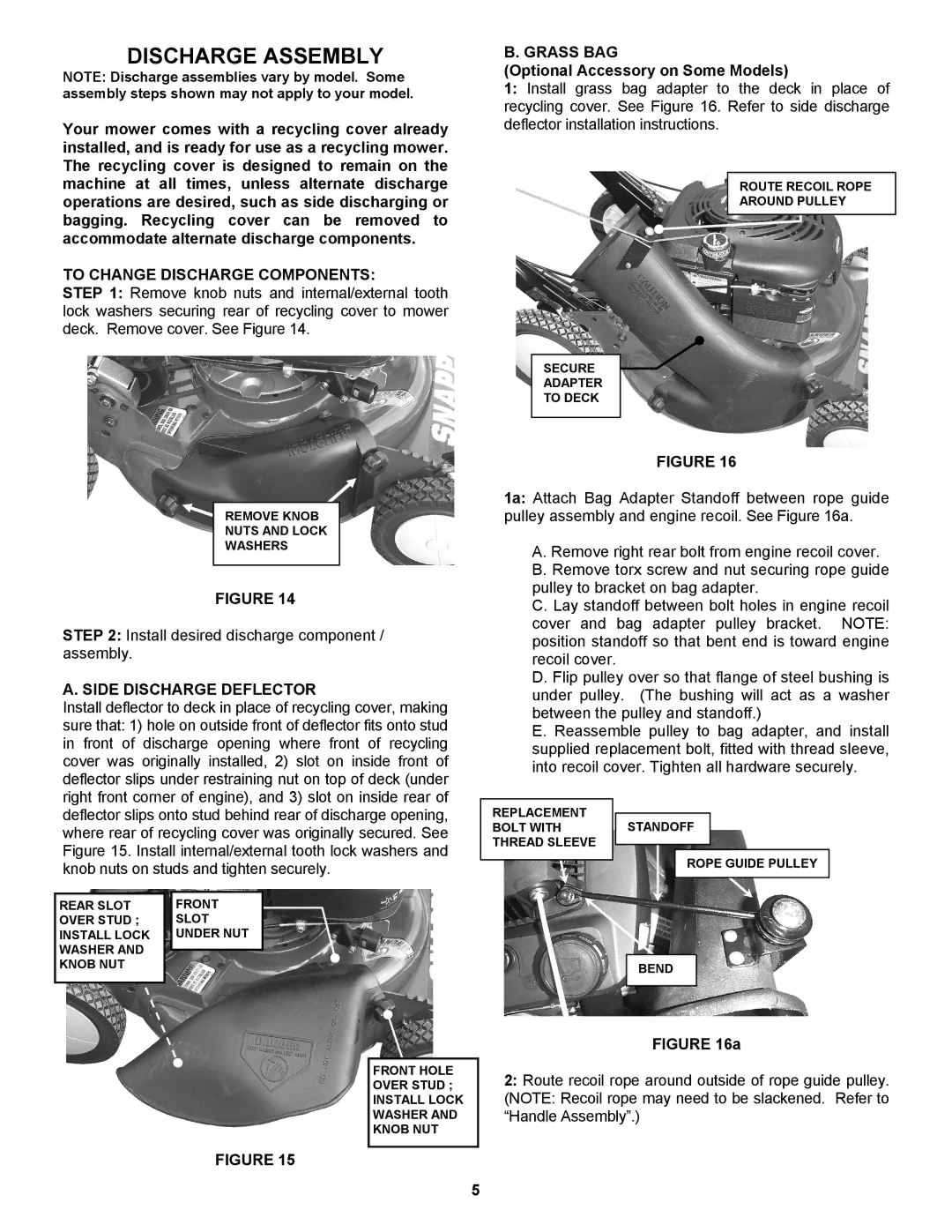
Snapper Lawn Mower is a well-regarded lawn care solution that has been trusted by homeowners and landscaping professionals alike for years. Known for its durability, performance, and innovative features, Snapper mowers stand out in a crowded market. One of the main attributes of Snapper mowers is their ease of use. Many models are designed with user-friendly controls, making them accessible to both novice and experienced operators. The intuitive design ensures comfortable handling, which is essential when tackling larger lawns.A key feature of Snapper mowers is their powerful engine options. Equipped with reliable Briggs & Stratton or Kawasaki engines, these mowers deliver the power necessary to tackle thick, overgrown grass with ease. This ensures consistent performance and efficiency, allowing users to complete their lawn care tasks quickly. Energy efficiency is also a priority, and many Snapper models boast fuel-efficient engines that save on gas while still providing robust power.
Snapper lawn mowers come with several cutting technologies, including their signature pivoting deck design. This allows for exceptional maneuverability and ensures a clean cut even on uneven terrain. The ability to adjust cutting heights easily lets users customize their mowing experience according to their lawn’s specific needs, whether it's maintaining a neat trim or cutting taller grass.
Another notable feature is Snapper’s innovative mulching capability. Most models have a built-in mulching blade system that finely chops grass clippings, allowing them to be returned to the soil and acting as a natural fertilizer. This promotes a healthy lawn while reducing the need for bagging and disposal. Additionally, Snapper mowers are available in both self-propelled and push models, catering to a variety of preferences and lawn sizes.
Durability is a hallmark of the Snapper brand. Constructed with robust materials and reinforced components, Snapper mowers are designed to withstand the rigors of frequent use. Many models come with rust-resistant decks, ensuring longevity and a reliable lawn care solution for years to come.
Finally, the convenience of maintenance features, such as tool-less blade removal and easy access to the engine, underscores Snapper’s commitment to user-friendly design. Overall, Snapper Lawn Mowers combine performance, efficiency, and user-centric features, making them an excellent choice for anyone looking to maintain a well-manicured lawn with ease.

