Section 5 - ADJUSTMENTS & REPAIR
DANGER
Exercise EXTREME CAUTION when making this adjustment, due to close proximity of moving parts.
5.1NEUTRAL POSITION ADJUSTMENTS
The joystick controls the movement and stopping of the machine. Move the joystick to the center or neutral position to stop machine. IMPORTANT:
Always return the joystick with hand assistance to the neutral position. If machine does not come to a complete stop or has any movement when joystick is moved to the neutral position, adjustment must be made.
1.Turn key to “OFF” position.
2.Raise both wheels off the ground. Wheels should be high enough to rotate freely. Secure with safety blocks.
3.Disconnect parking brake rod from parking brake. See Figure 4.3.
4.Engage parking brake lever. NOTE: Engaging parking brake without brake rod connected will lock joystick in center or neutral position.
5.Turn key to start position and start unit.
6.Both wheels should not have any movement, not rotating.
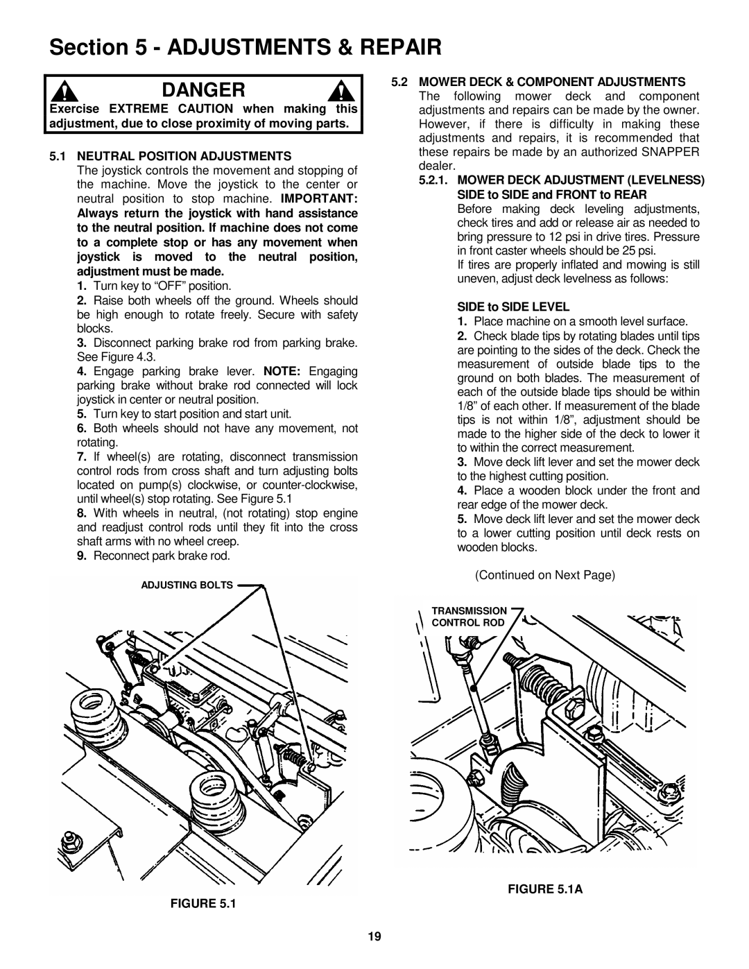
7.If wheel(s) are rotating, disconnect transmission control rods from cross shaft and turn adjusting bolts located on pump(s) clockwise, or
8.With wheels in neutral, (not rotating) stop engine and readjust control rods until they fit into the cross shaft arms with no wheel creep.
9.Reconnect park brake rod.
ADJUSTING BOLTS
5.2MOWER DECK & COMPONENT ADJUSTMENTS The following mower deck and component adjustments and repairs can be made by the owner. However, if there is difficulty in making these adjustments and repairs, it is recommended that these repairs be made by an authorized SNAPPER dealer.
5.2.1.MOWER DECK ADJUSTMENT (LEVELNESS) SIDE to SIDE and FRONT to REAR
Before making deck leveling adjustments, check tires and add or release air as needed to bring pressure to 12 psi in drive tires. Pressure in front caster wheels should be 25 psi.
If tires are properly inflated and mowing is still uneven, adjust deck levelness as follows:
SIDE to SIDE LEVEL
1.Place machine on a smooth level surface.
2.Check blade tips by rotating blades until tips are pointing to the sides of the deck. Check the measurement of outside blade tips to the ground on both blades. The measurement of each of the outside blade tips should be within 1/8” of each other. If measurement of the blade tips is not within 1/8”, adjustment should be made to the higher side of the deck to lower it to within the correct measurement.
3.Move deck lift lever and set the mower deck to the highest cutting position.
4.Place a wooden block under the front and rear edge of the mower deck.
5.Move deck lift lever and set the mower deck to a lower cutting position until deck rests on wooden blocks.
(Continued on Next Page)
TRANSMISSION
CONTROL ROD
FIGURE 5.1A
FIGURE 5.1
19