Section 3 - OPERATING INSTRUCTIONS
3.1PRE-START CHECK LIST
Make the following checks and perform the service required before each
3.1.1.Check tires and add or release air as needed to bring pressure to 12 psi in drive tires. Pressure in front deck caster wheels should be 25 psi.
3.1.2.Check guards, deflectors and covers to make sure all are in place and securely tightened.
3.1.3.Check engine oil and add oil as needed to bring level up to the FULL mark. Refer to engine owner’s manual for oil specifications. See Figure 3.1.
SAFE LEVEL
AREA
FIGURE 3.1
3.1.4.Check Blade switch to insure it works freely. Switch is pulled “OUT” for blade engagement or pushed back “IN” for blade disengagement. See Figure 3.2. IMPORTANT: Disengagement stops blades.
BLADE SWITCH
FIGURE 3.2
3.1.5.Clean exterior surfaces of cutting deck and engine of any accumulation of dirt, grass, oil, etc. Keep engine air intake screen and cooling fins clear at all times.
3.1.6.Add fuel to tank of the machine outside where fumes can safely dissipate. Make sure fuel filler cap is tight. Refer to engine owner’s manual for fuel specifications.
3.1.7.Adjust position of operator’s seat. The seat is mounted on slides. Locate latch lever beneath the seat. Move lever towards the left and slide seat to the desired position. Release latch.
3.1.8.Place mower in desired cutting height setting. Grasp deck lift lever and depress release button located at tip of lever. Move lever to desired setting, 1 thru 7, and release latch. See Figure 1.1.
IMPORTANT: This machine is equipped with hydrostatic drive. The forward and rearward movement of the mower is controlled by a joystick lever. Joystick operations should be performed only from the operator’s position in the seat. A small movement of the joystick can cause the machine to move instantly. Move joystick very carefully and slowly.
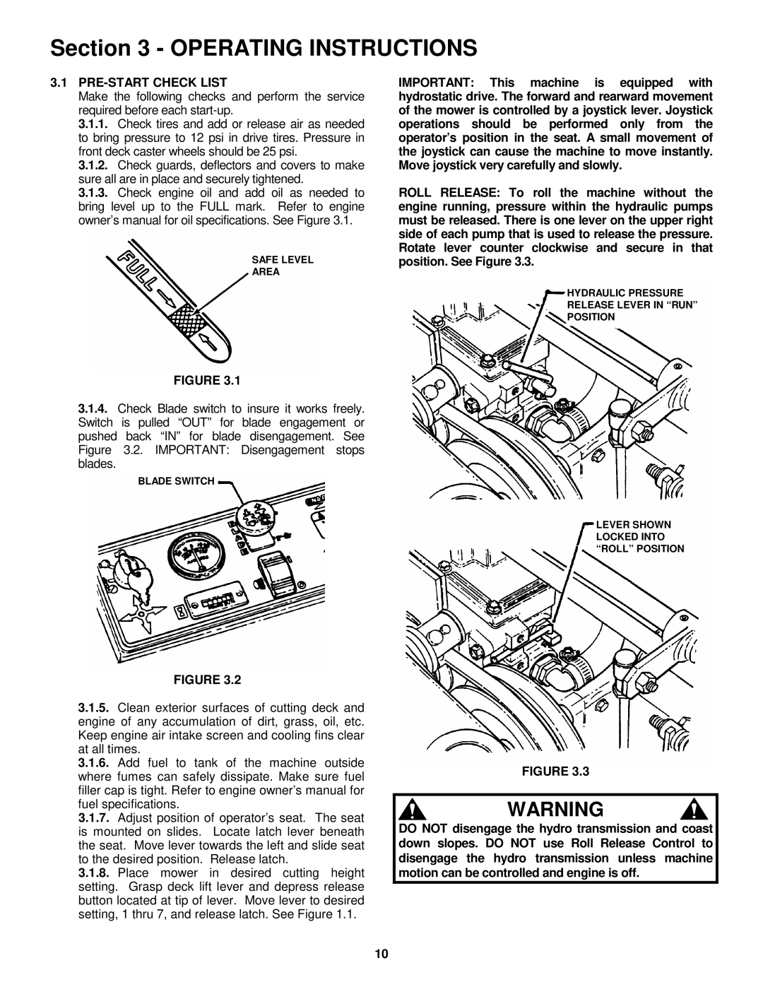
ROLL RELEASE: To roll the machine without the engine running, pressure within the hydraulic pumps must be released. There is one lever on the upper right side of each pump that is used to release the pressure. Rotate lever counter clockwise and secure in that position. See Figure 3.3.
HYDRAULIC PRESSURE
RELEASE LEVER IN “RUN”
POSITION
LEVER SHOWN LOCKED INTO “ROLL” POSITION
FIGURE 3.3
WARNING
DO NOT disengage the hydro transmission and coast down slopes. DO NOT use Roll Release Control to disengage the hydro transmission unless machine motion can be controlled and engine is off.
10