SECTION 4 – SERVICE
WARNING
Once blades are disengaged, they should come to a complete stop in 7 seconds or less. If the blades continue to rotate after 7 seconds, the electric clutch must be checked. Replacement of electric clutch may be necessary. Return machine to dealer for replacement. DO NOT CONTINUE to operate mower if blades fail to stop in 7 seconds.
4.1 ELECTRIC CLUTCH ADJUSTMENT
The Pro Hydro Mowers are equipped with an Electric Blade Control. The cutter blades should STOP within 7 seconds after the BLADE SWITCH is moved to “OFF” position. If blade stopping time exceeds 7 seconds, check the clutch air gap setting as follows:
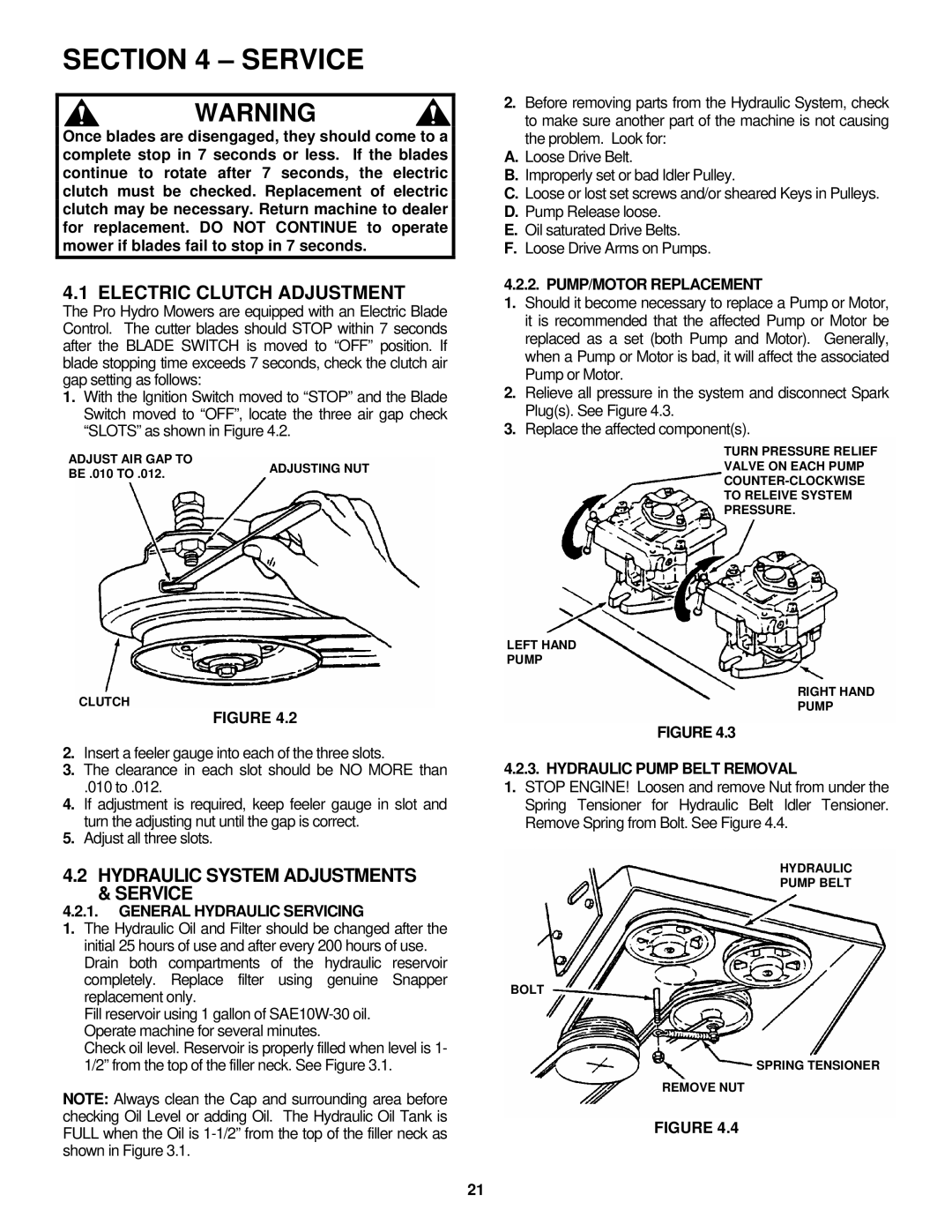
1.With the Ignition Switch moved to “STOP” and the Blade Switch moved to “OFF”, locate the three air gap check “SLOTS” as shown in Figure 4.2.
ADJUST AIR GAP TO | ADJUSTING NUT | |
BE .010 TO .012. | ||
|
CLUTCH
FIGURE 4.2
2.Insert a feeler gauge into each of the three slots.
3.The clearance in each slot should be NO MORE than
.010 to .012.
4.If adjustment is required, keep feeler gauge in slot and turn the adjusting nut until the gap is correct.
5.Adjust all three slots.
4.2 HYDRAULIC SYSTEM ADJUSTMENTS
&SERVICE
4.2.1.GENERAL HYDRAULIC SERVICING
1.The Hydraulic Oil and Filter should be changed after the initial 25 hours of use and after every 200 hours of use. Drain both compartments of the hydraulic reservoir completely. Replace filter using genuine Snapper replacement only.
Fill reservoir using 1 gallon of
Check oil level. Reservoir is properly filled when level is 1- 1/2” from the top of the filler neck. See Figure 3.1.
NOTE: Always clean the Cap and surrounding area before checking Oil Level or adding Oil. The Hydraulic Oil Tank is FULL when the Oil is
2.Before removing parts from the Hydraulic System, check to make sure another part of the machine is not causing the problem. Look for:
A.Loose Drive Belt.
B.Improperly set or bad Idler Pulley.
C.Loose or lost set screws and/or sheared Keys in Pulleys.
D.Pump Release loose.
E.Oil saturated Drive Belts.
F.Loose Drive Arms on Pumps.
4.2.2. PUMP/MOTOR REPLACEMENT
1.Should it become necessary to replace a Pump or Motor, it is recommended that the affected Pump or Motor be replaced as a set (both Pump and Motor). Generally, when a Pump or Motor is bad, it will affect the associated Pump or Motor.
2.Relieve all pressure in the system and disconnect Spark Plug(s). See Figure 4.3.
3.Replace the affected component(s).
TURN PRESSURE RELIEF
VALVE ON EACH PUMP
TO RELEIVE SYSTEM
PRESSURE.
LEFT HAND
PUMP
RIGHT HAND
PUMP
FIGURE 4.3
4.2.3. HYDRAULIC PUMP BELT REMOVAL
1.STOP ENGINE! Loosen and remove Nut from under the Spring Tensioner for Hydraulic Belt Idler Tensioner. Remove Spring from Bolt. See Figure 4.4.
HYDRAULIC
PUMP BELT
BOLT
SPRING TENSIONER
REMOVE NUT
FIGURE 4.4
21