Section 4 - ADJUSTMENTS & REPAIR
4.3.2.MOWER DRIVE BELT REPLACEMENT Inspect mower drive belt. Replace belt if signs of excessive wear and/or damage are present.
WARNING
Before attempting any adjustments or repairs, STOP the engine, remove the key, remove the spark plug wire(s) from the spark plug(s) and secure wire(s) away from plug(s).
4.3.3. BELT REMOVAL
1.Remove foot rest. Refer to Section 3.2.3. - Foot Rest Removal.
2.Remove old belt.
4.3.4. BELT REPLACEMENT
1.Route new belt around electric clutch pulley. See Figure 4.3.
MOWER
BELTROUTE MOWER BELT AROUND ELECTRIC CLUTCH PULLEY
BELT REPLACEMENTS
Engine to Hydro Pumps (All Models) | Part No. |
Engine to Electric Clutch (All Models) | Part No. |
Electric Clutch to Mower (33” Decks) | Part No. |
Electric Clutch to Mower (38” Decks) | Part No. |
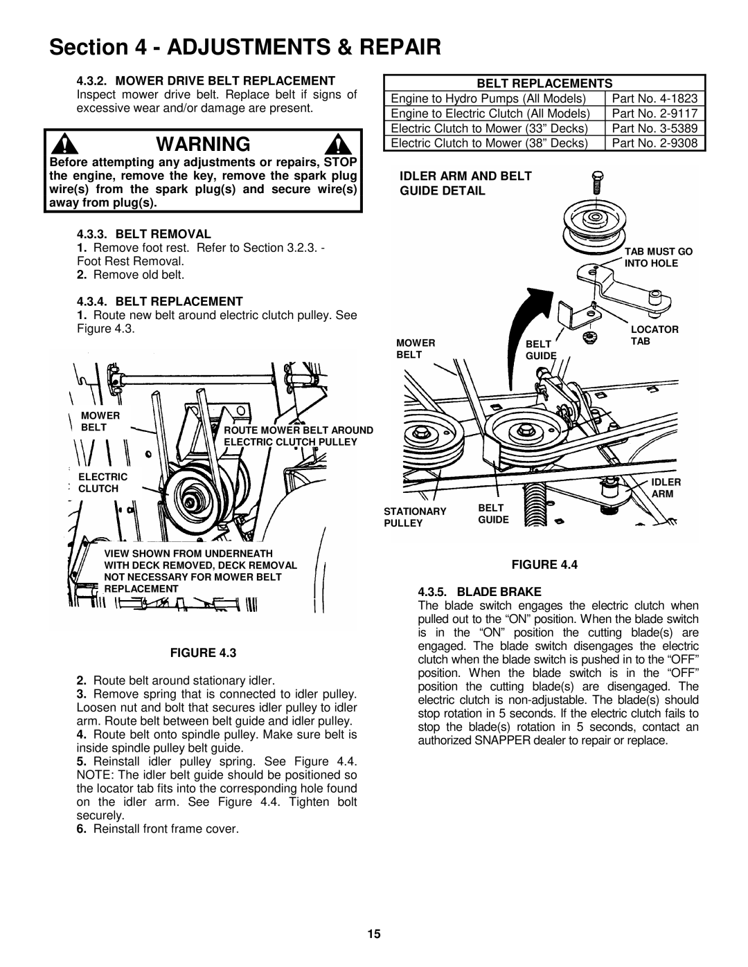
IDLER ARM AND BELT
GUIDE DETAIL
TAB MUST GO
INTO HOLE
|
| LOCATOR |
MOWER | BELT | TAB |
BELT | GUIDE |
|
ELECTRIC
CLUTCH
VIEW SHOWN FROM UNDERNEATH
WITH DECK REMOVED, DECK REMOVAL
NOT NECESSARY FOR MOWER BELT
REPLACEMENT
FIGURE 4.3
2.Route belt around stationary idler.
3.Remove spring that is connected to idler pulley. Loosen nut and bolt that secures idler pulley to idler arm. Route belt between belt guide and idler pulley.
4.Route belt onto spindle pulley. Make sure belt is inside spindle pulley belt guide.
5.Reinstall idler pulley spring. See Figure 4.4. NOTE: The idler belt guide should be positioned so the locator tab fits into the corresponding hole found on the idler arm. See Figure 4.4. Tighten bolt securely.
6.Reinstall front frame cover.
IDLER
ARM
STATIONARY BELT
PULLEYGUIDE
FIGURE 4.4
4.3.5. BLADE BRAKE
The blade switch engages the electric clutch when pulled out to the “ON” position. When the blade switch is in the “ON” position the cutting blade(s) are engaged. The blade switch disengages the electric clutch when the blade switch is pushed in to the “OFF” position. When the blade switch is in the “OFF” position the cutting blade(s) are disengaged. The electric clutch is
15