Section 4 - ADJUSTMENTS & REPAIR
WARNING
Before attempting any adjustments or repairs, STOP the engine, remove the key, remove the spark plug wire(s) from the spark plug(s) and secure wire(s) away from plug(s).
4.1 NEUTRAL POSITION ADJUSTMENTS
The joystick controls the movement and stopping of the unit. Move the joystick to the center or neutral position to stop mower. IMPORTANT: Always return the joystick with hand assistance to the neutral position. If mower does not come to a complete stop or has any movement when joystick is moved to the neutral position, adjustment must be made. It is recommended that these adjustments be made by an authorized SNAPPER dealer. But, adjust joystick cables as follows after removing fenders:
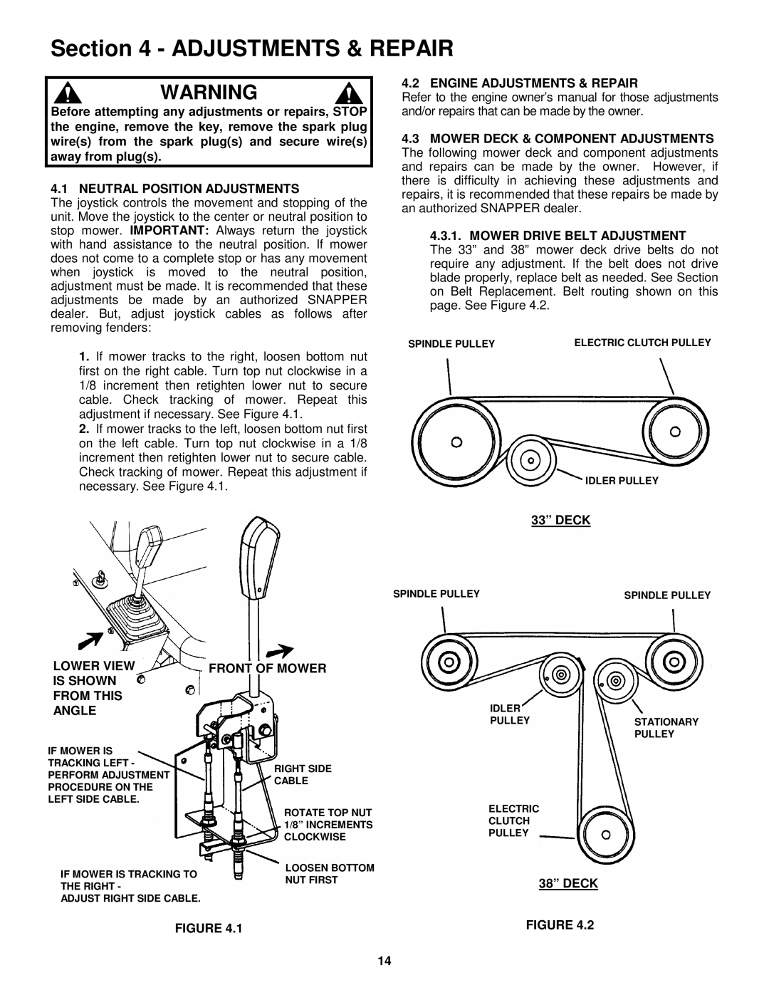
1.If mower tracks to the right, loosen bottom nut first on the right cable. Turn top nut clockwise in a 1/8 increment then retighten lower nut to secure cable. Check tracking of mower. Repeat this adjustment if necessary. See Figure 4.1.
2.If mower tracks to the left, loosen bottom nut first on the left cable. Turn top nut clockwise in a 1/8 increment then retighten lower nut to secure cable. Check tracking of mower. Repeat this adjustment if necessary. See Figure 4.1.
4.2 ENGINE ADJUSTMENTS & REPAIR
Refer to the engine owner’s manual for those adjustments and/or repairs that can be made by the owner.
4.3MOWER DECK & COMPONENT ADJUSTMENTS The following mower deck and component adjustments and repairs can be made by the owner. However, if there is difficulty in achieving these adjustments and repairs, it is recommended that these repairs be made by an authorized SNAPPER dealer.
4.3.1. MOWER DRIVE BELT ADJUSTMENT
The 33” and 38” mower deck drive belts do not require any adjustment. If the belt does not drive blade properly, replace belt as needed. See Section on Belt Replacement. Belt routing shown on this page. See Figure 4.2.
SPINDLE PULLEY | ELECTRIC CLUTCH PULLEY |
IDLER PULLEY
33” DECK
SPINDLE PULLEY | SPINDLE PULLEY |
LOWER VIEW | FRONT OF MOWER |
| |
IS SHOWN |
|
| |
FROM THIS |
| IDLER | |
ANGLE |
| ||
|
| PULLEY | |
IF MOWER IS |
|
| |
TRACKING LEFT - | RIGHT SIDE |
| |
PERFORM ADJUSTMENT |
| ||
CABLE |
| ||
PROCEDURE ON THE |
| ||
|
| ||
LEFT SIDE CABLE. |
| ELECTRIC | |
| ROTATE TOP NUT | ||
| CLUTCH | ||
| 1/8” INCREMENTS | ||
| PULLEY | ||
| CLOCKWISE | ||
|
| ||
IF MOWER IS TRACKING TO | LOOSEN BOTTOM |
| |
NUT FIRST | 38” DECK | ||
THE RIGHT - | |||
| |||
ADJUST RIGHT SIDE CABLE. |
|
| |
FIGURE 4.1 | FIGURE 4.2 | ||
STATIONARY PULLEY
14