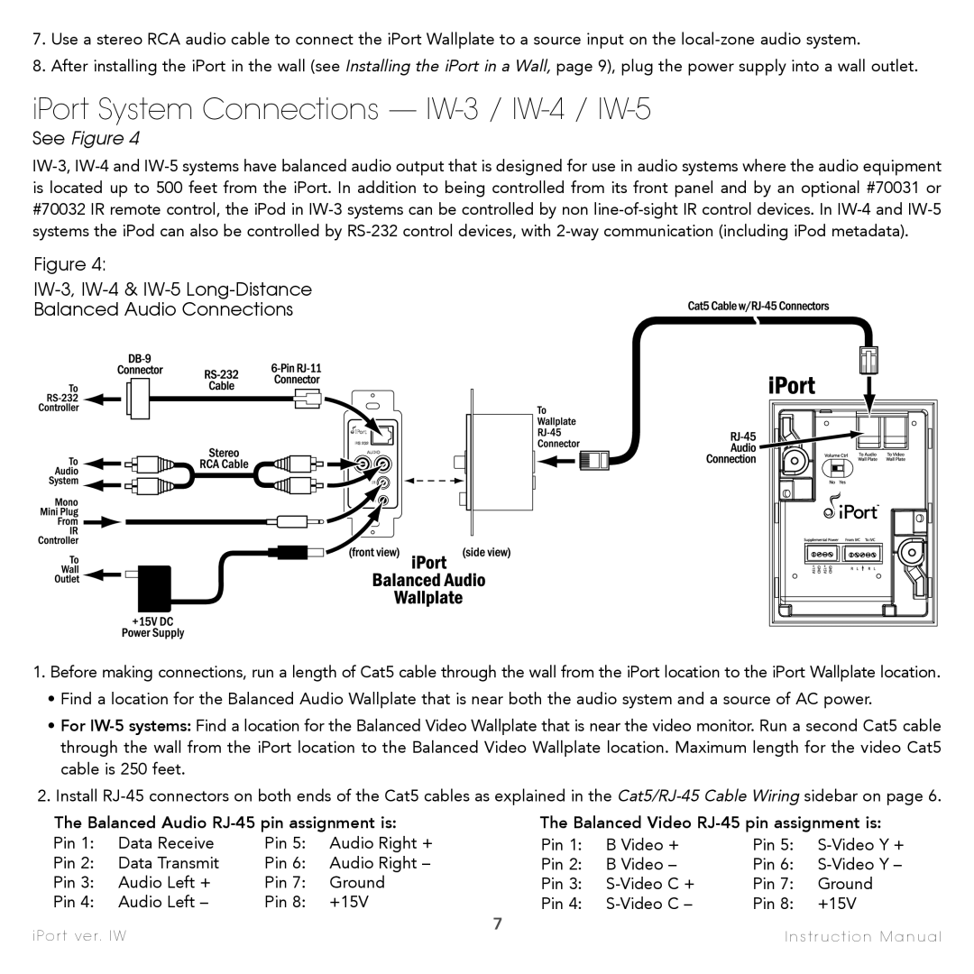
IW-5, IW-2, IW-4, IW-1, IW-3 specifications
Sonance is renowned for its commitment to delivering high-fidelity audio solutions that seamlessly blend into any living space. Among its impressive lineup of in-wall speakers, the IW series stands out, particularly the IW-1, IW-2, IW-3, IW-4, and IW-5 models. Each speaker is designed to enhance home audio experiences while maintaining a discreet aesthetic.The Sonance IW-1 is a compact in-wall speaker that prioritizes versatility. It features a 1-inch tweeter and a 5.25-inch mid/bass driver, which deliver crisp highs and robust mid-range frequencies. This model is particularly suitable for small to medium-sized rooms. The integration of Sonance's patented technology allows for easy installation and an impressive soundstage, ensuring that it doesn't compromise on performance despite its smaller size.
Moving to the IW-2, this model steps up with a larger 6.5-inch mid/bass driver, coupled with a 1-inch tweeter. This design provides enhanced low-frequency response, making it ideal for home theater systems. The IW-2 incorporates a unique tuning system that allows users to adjust the audio output to suit their specific environment, providing a tailored listening experience.
The IW-3 is designed for those who crave a more powerful output. Featuring dual 6.5-inch woofers and a 1-inch tweeter, the IW-3 ensures rich, cinematic audio quality and impressive bass response. Its robust build and quality materials contribute to its durability, making it an excellent choice for both residential and commercial spaces.
For audiophiles looking for an exceptional sound experience, the IW-4 offers even more sophistication. This model includes advanced crossover technology, providing seamless transitions between frequencies. The IW-4 boasts integrated back boxes that improve sound isolation and reduce distortion, enhancing overall performance.
Lastly, the IW-5 model is the flagship of the series, engineered for ultimate audio fidelity. This speaker features dual 8-inch woofers and high-performance tweeters, enabling it to deliver deep and powerful bass alongside crystal-clear highs. The IW-5 utilizes the latest sound dispersion technology, allowing for expansive sound coverage throughout larger spaces.
In summary, the Sonance IW series, including the IW-1, IW-2, IW-3, IW-4, and IW-5, offers a range of powerful in-wall speaker options tailored to diverse audio needs. With features like adjustable tuning systems, advanced crossover technology, and high-quality drivers, these speakers stand at the forefront of modern home audio solutions, ensuring that every listener enjoys a rich and immersive sound experience. Whether it’s for casual listening or creating an elaborate home theater, Sonance provides an exceptional choice for anyone looking to elevate their audio experience.

