Manuals
/
Sonic Impact Technologies
/
Home Audio
/
CD Player
Sonic Impact Technologies
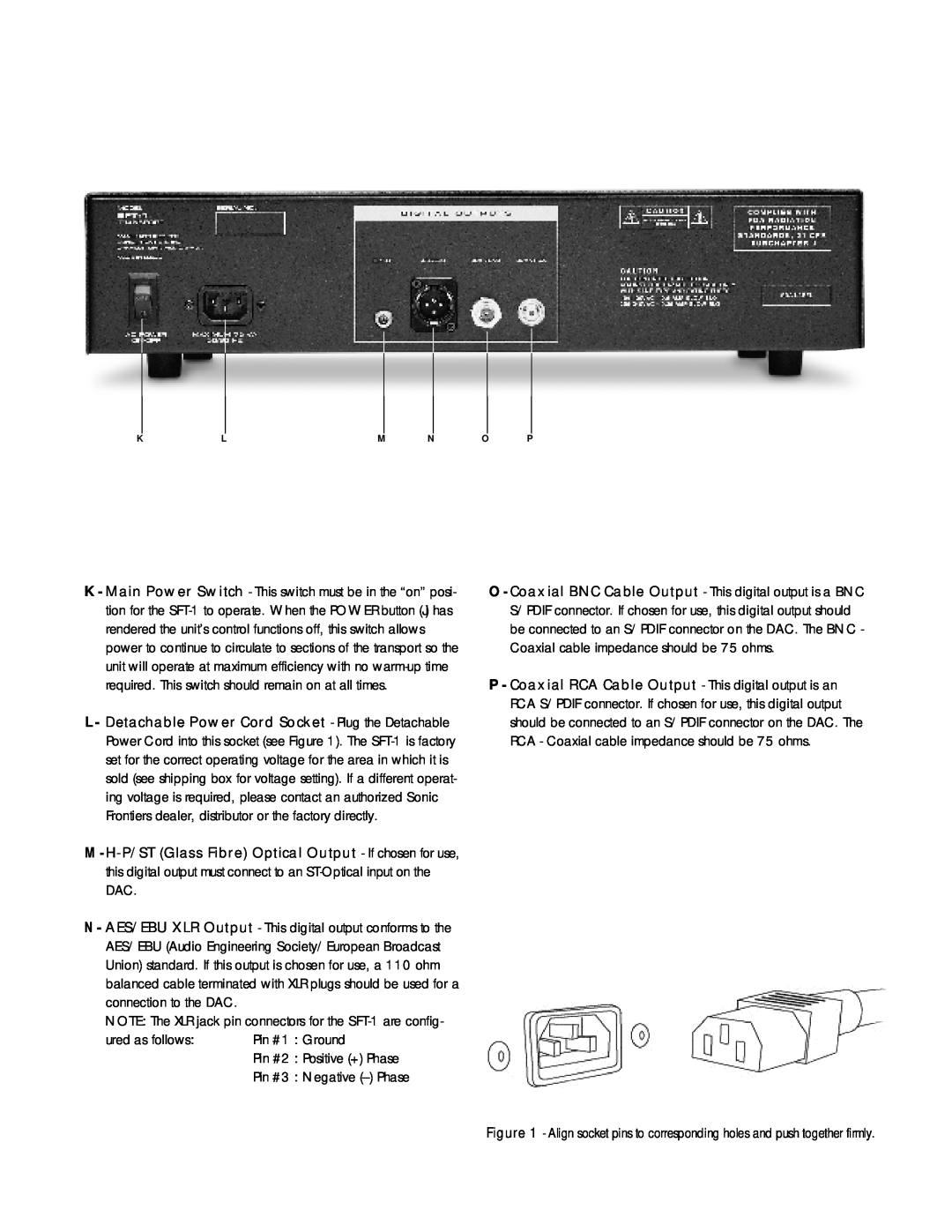
SFT-1 D A C, ured as follows Pin #1 Ground, Pin #2 Positive + Phase
Models:
SFT-1
1
3
8
8
Download
8 pages
35.85 Kb
1
2
3
4
5
6
7
8
Pin #2 Positive + Phase
Page 3
Image 3
Page 2
Page 4
Page 3
Image 3
Page 2
Page 4
Contents
THE SONIC FRONTIERS SFT - 1 TRANSPORT
OWNER’ S MANUAL
P R O G R A M, when these functions are selected
ured as follows Pin #1 Ground
Pin #2 Positive + Phase
Pin #3 Negative -Phase
D A C
FUNCTIONS OF THE SFT-1REMOTE CONTROL Q R
Load the Remote Control with 2 AAA size batteries
1.Warranty applies only to the original purchaser
Wow and Flutter
Top
Page
Image
Contents