DISASSEMBLY/PART NUMBER INFORMATION
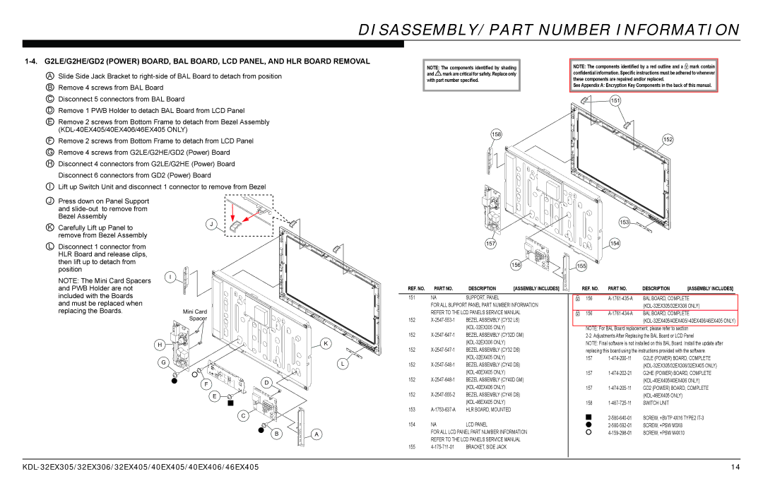
A | Slide Side Jack Bracket to |
B | Remove 4 screws from BAL Board |
NOTE: The components identified by shading |
| NOTE: The components identified by a red outline and a mark contain |
and ! mark are critical for safety. Replace only |
| confidential information. Specific instructions must be adhered to whenever |
with part number specified. |
| these components are repaired and/or replaced. |
|
| See Appendix A: Encryption Key Components in the back of this manual. |
|
|
|
C Disconnect 5 connectors from BAL Board | |
D Remove 1 PWB Holder to detach BAL Board from LCD Panel | |
E | Remove 2 screws from Bottom Frame to detach from Bezel Assembly |
| |
F | Remove 2 screws from Bottom Frame to detach from LCD Panel |
GRemove 4 screws from G2LE/G2HE/GD2 (Power) Board
HDisconnect 4 connectors from G2LE/G2HE (Power) Board
Disconnect 6 connectors from GD2 (Power) Board
I Lift up Switch Unit and disconnect 1 connector to remove from Bezel
J | Press down on Panel Support |
| |
| and |
| |
| Bezel Assembly | J | |
K | Carefully Lift up Panel to | ||
| |||
| remove from Bezel Assembly |
|
158 |
151 |
152 |
153 |
L Disconnect 1 connector from |
HLR Board and release clips, |
then lift up to detach from |
position |
NOTE: The Mini Card Spacers |
and PWB Holder are not |
I![]()
![]()
![]()
156 |
REF. NO. | PART NO. | DESCRIPTION | [ASSEMBLY INCLUDES] |
155 |
REF. NO. | PART NO. | DESCRIPTION | [ASSEMBLY INCLUDES] |
included with the Boards |
and must be replaced when |
replacing the Boards. |
Mini Card
Spacer
151 | NA | SUPPORT, PANEL |
| FOR ALL SUPPORT PANEL PART NUMBER INFORMATION | |
| REFER TO THE LCD PANELS SERVICE MANUAL | |
152 | BEZEL ASSEMBLY (CY32 LS) | |
|
| |
156
156 | BAL BOARD, COMPLETE | |
|
|
NOTE: For BAL Board replacement, please refer to section
H |
G |
F
E |
D |
C |
B |
K |
L |
A |
152 | BEZEL ASSEMBLY (CY32D GM) | |
|
| |
152 | BEZEL ASSEMBLY (CY32 DS) | |
|
|
152
152
152
153
154 | NA | LCD PANEL |
| FOR ALL LCD PANEL PART NUMBER INFORMATION | |
| REFER TO THE LCD PANELS SERVICE MANUAL | |
155 | BRACKET, SIDE JACK | |
NOTE: Final software is not installed on this BAL Board. Install the update after replacing this board using the instructions provided with the software.
157
157 |
| G2HE (POWER) BOARD, COMPLETE |
|
|
157
158 | SWITCH UNIT | ||
|
| SCREW, +BVTP 4X16 TYPE2 | |
|
| ||
|
| ||
|
| SCREW, +PSW M3X8 | |
|
| SCREW, +PSW M4X10 | |
14 |