Location and Functions of Parts
Front Panel
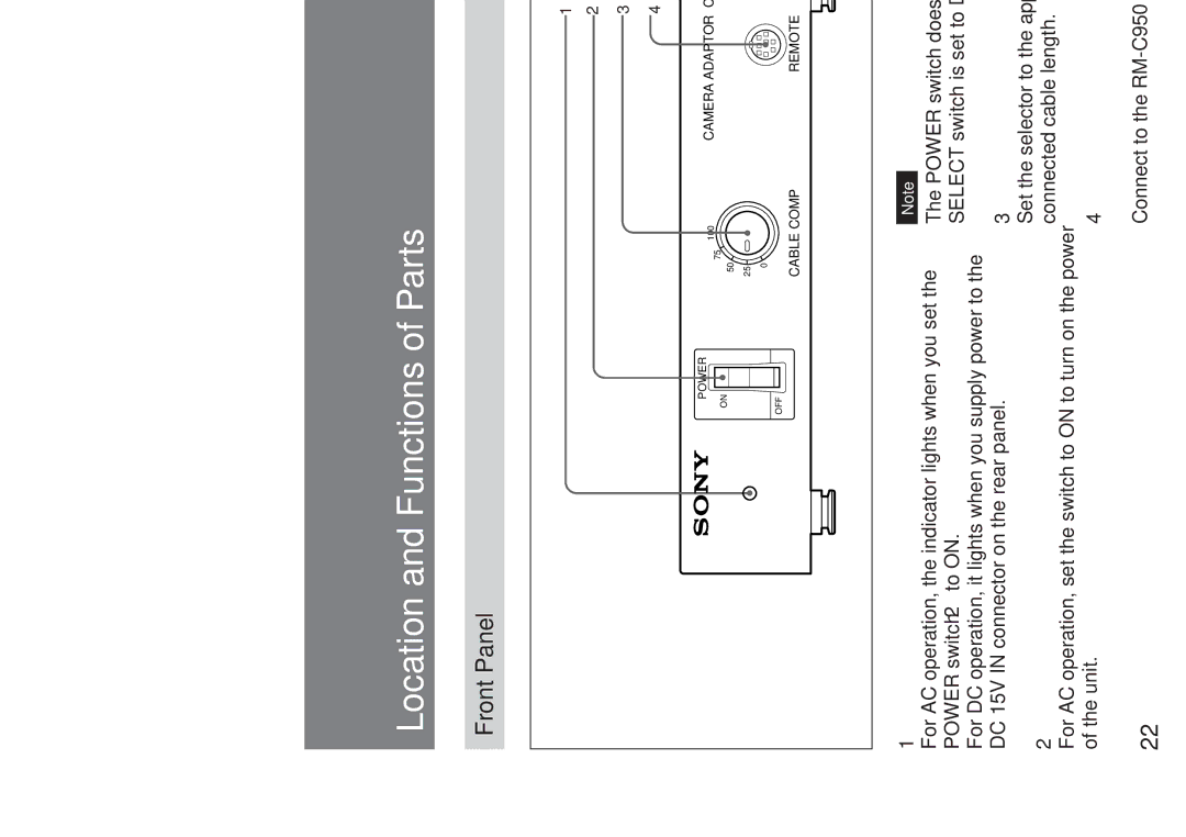
1 Power indicator
2 POWER switch
3 CABLE COMP selector
4 REMOTE connector
POWER | CAMERA ADAPTOR |
100 | |
75 |
|
ON |
|
50 |
|
25 |
|
0 |
|
OFF |
|
CABLE COMP | REMOTE |
1Power indicator
For AC operation, the indicator lights when you set the POWER switch 2 to ON.
For DC operation, it lights when you supply power to the DC 15V IN connector on the rear panel.
2POWER switch
For AC operation, set the switch to ON to turn on the power of the unit.
22
Note
The POWER switch does not operate when the DC/AC SELECT switch is set to DC.
3CABLE COMP (cable compensation) selector
Set the selector to the appropriate position according to the connected cable length.
4REMOTE (remote control) connector (mini DIN, 8- pin)
Connect to the
