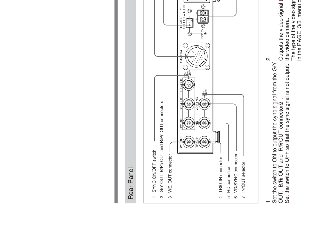
Rear Panel
1SYNC ON/OFF switch
2G/Y OUT, B/PB OUT and R/PR OUT connectors
3WE. OUT connector
8CAMERA connector
9DC/AC SELECT switch
WE.OUT | G/Y OUT | B/PB OUT R/PR OUT | CAMERA | DC/AC | ~ |
|
|
| SYNC | SELECT | AC IN |
|
|
| ON |
|
|
|
|
| OFF |
|
|
TRIG IN | HD | VD/SYNC |
|
|
|
|
| IN |
| DC15V |
|
|
|
| IN |
| |
|
| OUT |
|
|
4TRIG IN connector
5HD connector
6VD/SYNC connector
7IN/OUT selector
!¼ AC IN connector
!Á DC 15 V IN connector
1SYNC ON/OFF switch
Set the switch to ON to output the sync signal from the G/Y OUT, B/PB OUT and R/PR OUT connectors 2.
Set the switch to OFF so that the sync signal is not output.
2G/Y OUT, B/PB OUT and R/PR OUT (video signal output) connectors (BNC type)
Outputs the video signal (GBR or Y/PB/PR) supplied from the video camera.
The type of the video signal is set by the GBR/YPBPR item in the PAGE 3/3 menu of the video camera.
23
