#2 SECTION 4 | |
| ADJUSTMENTS |
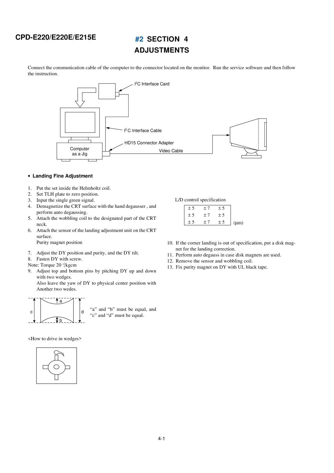
Connect the communication cable of the computer to the connector located on the monitor. Run the service software and then follow the instruction.
I2C Interface Card
I2 C Interface Cable
HD15 Connector Adapter
Computer ![]() Video Cable
Video Cable
as a Jig
•Landing Fine Adjustment
1.Put the set inside the Helmholtz coil.
2.Set TLH plate to zero position.
3.Input the single green signal.
4.Demagnetize the CRT surface with the hand degausser , and perform auto degaussing.
5.Attach the wobbling coil to the designated part of the CRT neck.
6.Attach the sensor of the landing adjustment unit on the CRT surface.
Purity magnet position
7.Adjust the DY position and purity, and the DY tilt.
8.Fasten DY with screw.
Note: Torque 20
9.Adjust top and bottom pins by pitching DY up and down with two wedges.
Also leave the yaw of DY to physical center position with Another two wedes.
| a |
|
|
c |
| d | “a” and “b” must be equal, and |
| “c” and “d” must be equal. | ||
| b |
| |
|
|
|
L/D control specification
± | 5 | ± | 7 | ± | 5 |
|
± | 5 | ± | 7 | ± | 5 |
|
± | 5 | ± | 7 | ± | 5 | (∝ m) |
10.If the corner landing is out of specification, put a disk mag- net for the landing correction.
11.Perform auto degauss in case disk magnets are used.
12.Remove the sensor and wobbling coil.
13.Fix purity magnet on DY with UL black tape.
<How to drive in wedges>