SAFETY CHECK-OUT
After correcting the original service problem, perform the fol- lowing safety checks before releasing the set to the customer:
1.Check the area of your repair for unsoldered or
2.Check the interboard wiring to ensure that no wires are “pinched” or contact
3.Check that all control knobs, shields, covers, ground straps, and mounting hardware have been replaced. Be absolutely certain that you have replaced all the insulators.
4.Look for unauthorized replacement parts, particularly tran- sistors, that were installed during a previous repair. Point them out to the customer and recommend their replacement.
5.Look for parts which, though functioning, show obvious signs of deterioration. Point them out to the customer and recommend their replacement.
6.Check the line cords for cracks and abrasion. Recommend the replacement of any such line cord to the customer.
7.Check the B+ and HV to see if they are specified values. Make sure your instruments are accurate; be suspicious of your HV meter if sets always have low HV.
8.Check the antenna terminals, metal trim, “metallized” knobs, screws, and all other exposed metal parts for AC Leakage. Check leakage as described below.
To Exposed Metal
Parts on Set
| ∝ F |
|
|
|
| Ω | AC |
|
0.15 |
|
|
| 1.5 k | Voltmete | r | ||
|
|
|
|
|
|
| (0.75 V) |
|
|
|
|
|
|
|
|
|
|
Earth Ground
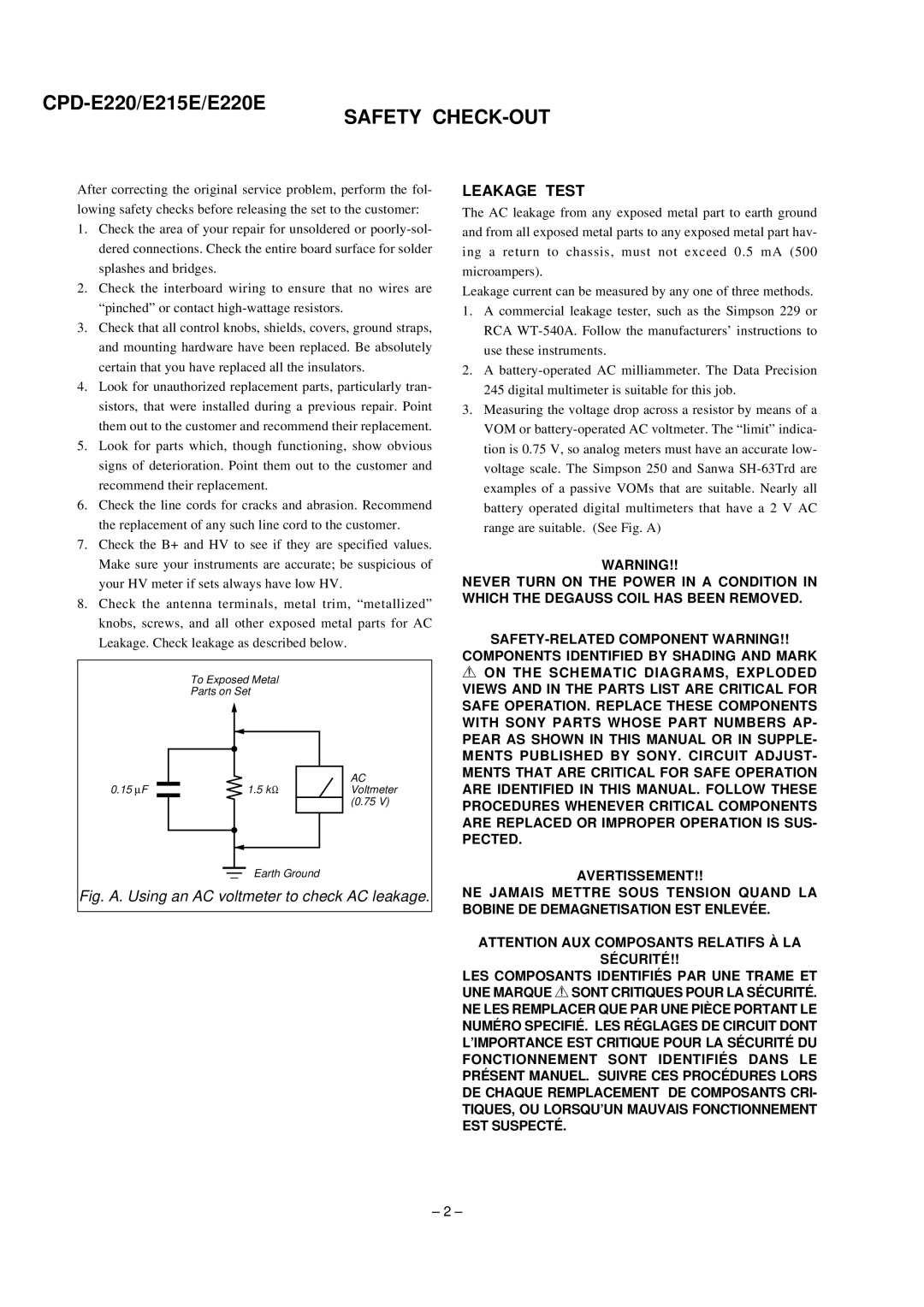
Fig. A. Using an AC voltmeter to check AC leakage.
LEAKAGE TEST
The AC leakage from any exposed metal part to earth ground and from all exposed metal parts to any exposed metal part hav- ing a return to chassis, must not exceed 0.5 mA (500 microampers).
Leakage current can be measured by any one of three methods.
1.A commercial leakage tester, such as the Simpson 229 or RCA
2.A
3.Measuring the voltage drop across a resistor by means of a VOM or
WARNING!!
NEVER TURN ON THE POWER IN A CONDITION IN WHICH THE DEGAUSS COIL HAS BEEN REMOVED.
COMPONENTS IDENTIFIED BY SHADING AND MARK
0ON THE SCHEMATIC DIAGRAMS, EXPLODED VIEWS AND IN THE PARTS LIST ARE CRITICAL FOR SAFE OPERATION. REPLACE THESE COMPONENTS WITH SONY PARTS WHOSE PART NUMBERS AP- PEAR AS SHOWN IN THIS MANUAL OR IN SUPPLE- MENTS PUBLISHED BY SONY. CIRCUIT ADJUST- MENTS THAT ARE CRITICAL FOR SAFE OPERATION ARE IDENTIFIED IN THIS MANUAL. FOLLOW THESE PROCEDURES WHENEVER CRITICAL COMPONENTS ARE REPLACED OR IMPROPER OPERATION IS SUS- PECTED.
AVERTISSEMENT!!
NE JAMAIS METTRE SOUS TENSION QUAND LA BOBINE DE DEMAGNETISATION EST ENLEVÉE.
ATTENTION AUX COMPOSANTS RELATIFS À LA
SÉCURITÉ!!
LES COMPOSANTS IDENTIFIÉS PAR UNE TRAME ET UNE MARQUE 0SONT CRITIQUES POUR LA SÉCURITÉ.
NE LES REMPLACER QUE PAR UNE PIÈCE PORTANT LE NUMÉRO SPECIFIÉ. LES RÉGLAGES DE CIRCUIT DONT L’IMPORTANCE EST CRITIQUE POUR LA SÉCURITÉ DU FONCTIONNEMENT SONT IDENTIFIÉS DANS LE PRÉSENT MANUEL. SUIVRE CES PROCÉDURES LORS DE CHAQUE REMPLACEMENT DE COMPOSANTS CRI- TIQUES, OU LORSQU’UN MAUVAIS FONCTIONNEMENT EST SUSPECTÉ.
– 2 –