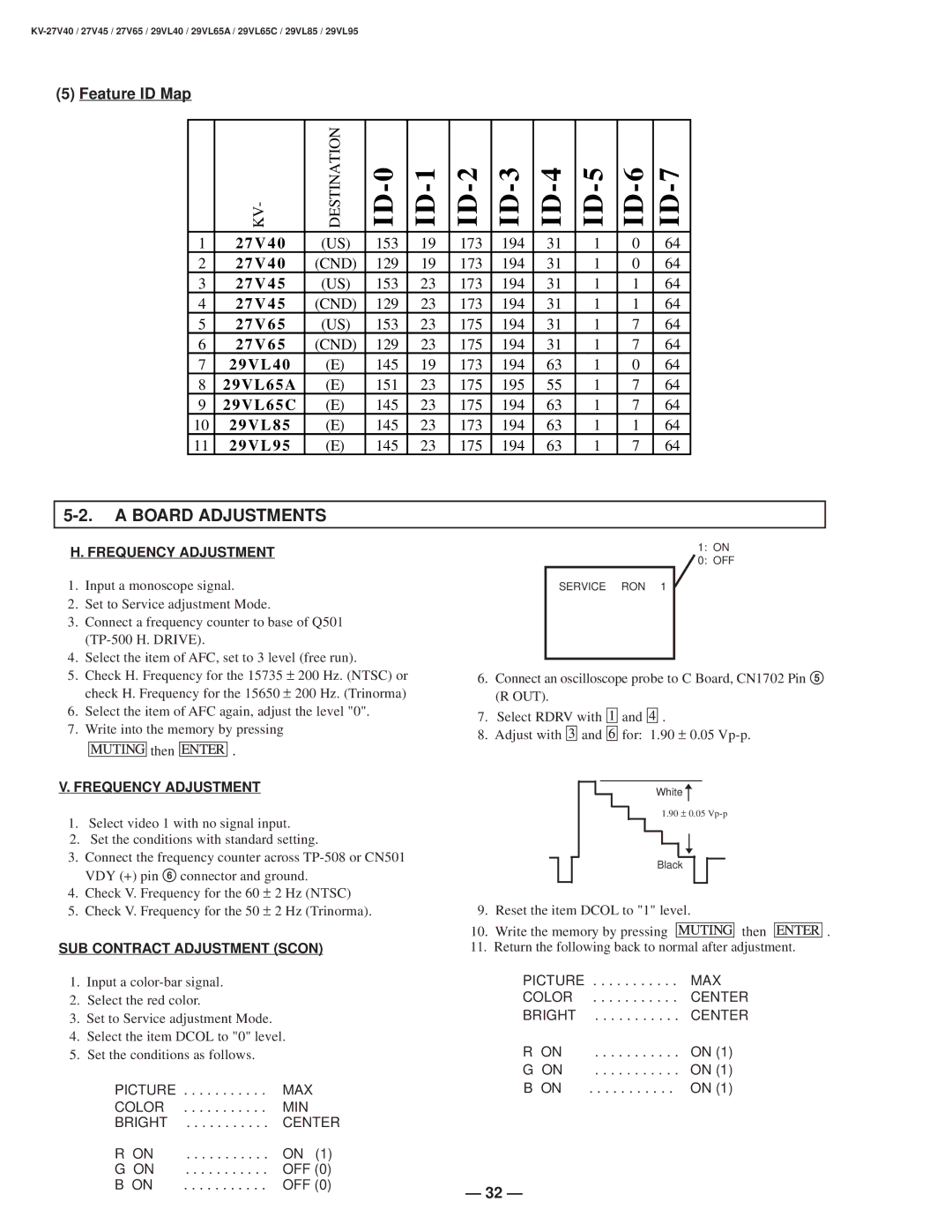
(5) Feature ID Map
| KV- | DESTINATION |
|
|
|
|
|
|
|
|
|
|
|
|
|
|
|
|
|
|
|
1 | 2 7 V 4 0 | (US) | 153 | 19 | 173 | 194 | 31 | 1 | 0 | 64 |
2 | 2 7 V 4 0 | (CND) | 129 | 19 | 173 | 194 | 31 | 1 | 0 | 64 |
3 | 2 7 V 4 5 | (US) | 153 | 23 | 173 | 194 | 31 | 1 | 1 | 64 |
4 | 2 7 V 4 5 | (CND) | 129 | 23 | 173 | 194 | 31 | 1 | 1 | 64 |
5 | 2 7 V 6 5 | (US) | 153 | 23 | 175 | 194 | 31 | 1 | 7 | 64 |
6 | 2 7 V 6 5 | (CND) | 129 | 23 | 175 | 194 | 31 | 1 | 7 | 64 |
7 | 2 9 V L 4 0 | (E) | 145 | 19 | 173 | 194 | 63 | 1 | 0 | 64 |
8 | 2 9 V L 6 5 A | (E) | 151 | 23 | 175 | 195 | 55 | 1 | 7 | 64 |
9 | 2 9 V L 6 5 C | (E) | 145 | 23 | 175 | 194 | 63 | 1 | 7 | 64 |
10 | 2 9 V L 8 5 | (E) | 145 | 23 | 173 | 194 | 63 | 1 | 1 | 64 |
11 | 2 9 V L 9 5 | (E) | 145 | 23 | 175 | 194 | 63 | 1 | 7 | 64 |
5-2. A BOARD ADJUSTMENTS
H. FREQUENCY ADJUSTMENT
1.Input a monoscope signal.
2.Set to Service adjustment Mode.
3.Connect a frequency counter to base of Q501
4.Select the item of AFC, set to 3 level (free run).
5.Check H. Frequency for the 15735 ± 200 Hz. (NTSC) or check H. Frequency for the 15650 ± 200 Hz. (Trinorma)
6.Select the item of AFC again, adjust the level "0".
7.Write into the memory by pressing
![]()
![]()
![]() then
then ![]()
![]()
![]() .
.
V. FREQUENCY ADJUSTMENT
1.Select video 1 with no signal input.
2.Set the conditions with standard setting.
3.Connect the frequency counter across
4.Check V. Frequency for the 60 ± 2 Hz (NTSC)
5.Check V. Frequency for the 50 ± 2 Hz (Trinorma).
SUB CONTRACT ADJUSTMENT (SCON)
1.Input a
2.Select the red color.
3.Set to Service adjustment Mode.
4.Select the item DCOL to "0" level.
5.Set the conditions as follows.
PICTURE | MAX |
COLOR | MIN |
BRIGHT | CENTER |
R ON | ON (1) |
G ON | OFF (0) |
B ON | OFF (0) |
1: ON
0: OFF
SERVICE RON 1
6.Connect an oscilloscope probe to C Board, CN1702 Pin 5 (R OUT).
7.Select RDRV with ![]()
![]()
![]() and
and ![]()
![]()
![]() .
.
8.Adjust with ![]()
![]()
![]() and
and ![]()
![]()
![]() for: 1.90 ± 0.05
for: 1.90 ± 0.05
Whiten
1.90 ± 0.05
![]()
![]()
![]() n
n
Black
9.Reset the item DCOL to "1" level.
10.Write the memory by pressing ![]()
![]()
![]() then
then ![]()
![]()
![]() .
.
11.Return the following back to normal after adjustment.
PICTURE | MAX |
COLOR | CENTER |
BRIGHT | CENTER |
R ON | ON (1) |
G ON | ON (1) |
B ON | ON (1) |
— 32 —