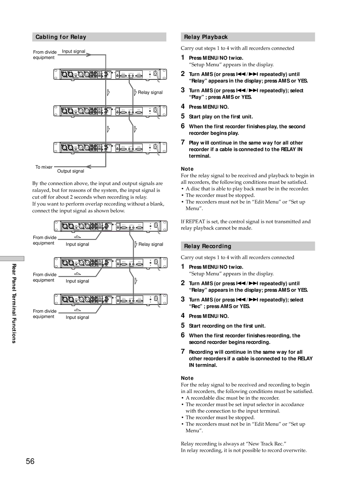
MDS-E12 specifications
The Sony MDS-E12 is a notable addition to the Minidisc player lineup, reflecting Sony's commitment to innovation in the digital audio realm. Released in the late 1990s, this device was designed with a focus on high-quality audio playback and recording, making it a preferred choice for audiophiles and professionals alike.One of the standout features of the MDS-E12 is its playback precision. Utilizing Sony's proprietary ATRAC (Adaptive TRansform Acoustic Coding) technology, the device processes audio with remarkable fidelity. ATRAC allows for efficient compression of audio files while maintaining impressive sound quality, making the MDS-E12 suitable for both casual listeners and serious music enthusiasts who demand clarity and rich soundscapes from their recordings.
In addition to its playback capabilities, the MDS-E12 also offers seamless recording features. Users can record live audio directly onto the Minidisc, capturing concerts, lectures, or personal performances with ease. The device supports both digital and analog input, allowing for versatile recording options from various audio sources. The built-in microphone input ensures that spontaneous recording is always an option.
Another highlight of the MDS-E12 is its user-friendly interface. The device includes a well-designed LCD display that provides essential information such as track numbers, play time, and remaining recording capacity. The intuitive layout of controls ensures that users can navigate easily through menus and settings, enhancing the overall user experience.
Moreover, the MDS-E12 incorporates a range of playback options. Users can enjoy repeat play, shuffle mode, and program play to customize their listening experience. The ability to label tracks enhances organization, allowing users to manage their collections effectively.
The Sony MDS-E12 is also built with durability in mind. Its robust design can withstand the rigors of daily use, catering to both home listeners and those on the go. The compact size of the device makes it portable, which is ideal for users who appreciate the flexibility of enjoying their audio on various occasions.
In terms of connectivity, the MDS-E12 features optical and coaxial digital outputs, as well as a headphone jack, making it straightforward to integrate with other audio equipment. Its performance, combined with comprehensive features and great sound quality, solidifies the Sony MDS-E12's place in the digital audio history, representing an era where Minidisc technology provided a fresh alternative to cassette tapes and CDs.

