TABLE OF CONTENTS


1.

GENERAL


Location of Controls

3


Setting the Clock

3


Installation

4


Connections

5

2.

DISASSEMBLY

9

3.ELECTRICAL ADJUSTMENTS

Test Mode

16

MD Section

16

Tuner Section

16

4.DIAGRAMS

4-1.

Block Diagram – SERVO Section

17

4-2.

Block Diagram – TUNER Section

18

4-3.

Block Diagram – MAIN Section

19

4-4.

Block Diagram – BUS CONTROL/


POWER SUPPLY Section

20

4-5.

Note for Printed Wiring Boards and


Schematic Diagrams

21

4-6.

Printed Wiring Boards


– SERVO Board (Component Side)/


SENSOR Board

22

4-7.

Printed Wiring Board


– SERVO Board (Conductor Side)

23

4-8. Schematic Diagram – SERVO Board (1/2)

24

4-9. Schematic Diagram – SERVO Board (2/2)

25

4-10.

Printed Wiring Board


– MAIN Board (Component Side)

26

4-11.

Printed Wiring Board


– MAIN Board (Conductor Side)

27

4-12.

Schematic Diagram – MAIN Board (1/3)

28

4-13.

Schematic Diagram – MAIN Board (2/3)

29

4-14.

Schematic Diagram – MAIN Board (3/3)

30

4-15.

Printed Wiring Board – SUB Board

32

4-16.

Schematic Diagram – SUB Board

33

4-17.

Printed Wiring Board – KEY Board

34

4-18.

Schematic Diagram – KEY Board

35

4-19. IC Pin Function Description

40

5.

EXPLODED VIEWS

50

6.

ELECTRICAL PARTS LIST

54

NOTES ON HANDLING THE OPTICAL PICK-UP BLOCK OR BASE UNIT

The laser diode in the optical pick-up block may suffer electro- static break-down because of the potential difference generated by the charged electrostatic load, etc. on clothing and the human body.

During repair, pay attention to electrostatic break-down and also use the procedure in the printed matter which is included in the repair parts.

The flexible board is easily damaged and should be handled with care.

NOTES ON LASER DIODE EMISSION CHECK

Never look into the laser diode emission from right avove when checking it for adustment. It is feared that you will lose your sight.

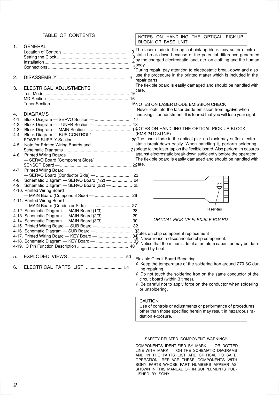
NOTES ON HANDLING THE OPTICAL PICK-UP BLOCK (KMS-241C/J1NP).

The laser diode in the optical pick-up block may suffer electro- static break-down easily. When handling it, perform soldering bridge to the laser-tap on the flexible board. Also perform m easures against electrostatic break-down sufficiently before the operation. The flexible board is easily damaged and should be handled with care.

laser-tap

OPTICAL PICK-UP FLEXIBLE BOARD

Notes on chip component replacement

Never reuse a disconnected chip component.

Notice that the minus side of a tantalum capacitor may be dam- aged by heat.

Flexible Circuit Board Repairing

Keep the temperature of the soldering iron around 270 ˚C dur- ing repairing.

Do not touch the soldering iron on the same conductor of the circuit board (within 3 times).

Be careful not to apply force on the conductor when soldering or unsoldering.

CAUTION

Use of controls or adjustments or performance of procedures other than those specified herein may result in hazardous ra- diation exposure.

SAFETY-RELATED COMPONENT WARNING!!

COMPONENTS IDENTIFIED BY MARK 0 OR DOTTED LINE WITH MARK 0 ON THE SCHEMATIC DIAGRAMS

AND IN THE PARTS LIST ARE CRITICAL TO SAFE OPERATION. REPLACE THESE COMPONENTS WITH SONY PARTS WHOSE PART NUMBERS APPEAR AS SHOWN IN THIS MANUAL OR IN SUPPLEMENTS PUB- LISHED BY SONY.

2

Page 2
Image 2
Sony MDX-C6500RV Table of Contents General, Electrical Adjustments, Diagrams, Flexible Circuit Board Repairing

MDX-C6500RV specifications

The Sony MDX-C6500RV is an advanced car audio receiver that combines cutting-edge technology with a user-friendly interface to enhance your driving experience. Designed for audiophiles and casual listeners alike, this model supports a plethora of formats and offers a range of features that ensure high-quality sound reproduction.

One of the key features of the MDX-C6500RV is its compatibility with the MiniDisc format, which allows for high-quality digital audio recording and playback. This makes it an ideal choice for music enthusiasts who appreciate finer sound details. The receiver also supports traditional CD playback, giving users the flexibility to enjoy their favorite albums and compilations effortlessly.

Equipped with a built-in FM/AM tuner, the MDX-C6500RV offers access to a vast array of radio stations. The tuner is enhanced with features such as RDS (Radio Data System), which provides additional information like station name and song details, making it easier to find your desired content.

The MDX-C6500RV comes with a powerful 52 Watts x 4 amplifier, ensuring that your music plays at optimal levels without distortion. It also features customizable equalizer settings with multiple presets, allowing users to tailor the sound profile to their unique listening preferences.

Another standout characteristic is the unit's front-facing auxiliary input, which enables direct connections to external devices such as smartphones and portable media players. This enhances versatility and allows for seamless integration of modern devices into your audio system. Additionally, the MDX-C6500RV is equipped with a USB port for convenient playback of digital files.

In terms of connectivity, the MDX-C6500RV includes options for both Bluetooth and wired integration, supporting hands-free calling and audio streaming. This ensures that drivers can stay connected and focused on the road while enjoying their favorite tracks.

The display is easy to read, featuring a vibrant backlight that ensures visibility even in low-light conditions. The user interface is intuitive, allowing for quick navigation through various functions and settings.

In summary, the Sony MDX-C6500RV blends functionality with high-performance audio features. With its MiniDisc support, powerful amplifier, customizable sound settings, and modern connectivity options, it stands out as a premium choice for car audio enthusiasts looking to enhance their in-car entertainment experience.