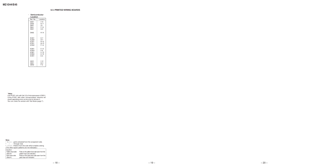
6-3. PRINTED WIRING BOARDS
rSemiconductor Location
Ref. No. | Location |
|
|
D351 | |
D352 | |
D801 | |
D841 | |
D901 | |
D902 | |
IC301 | |
IC302 | |
IC501 | |
IC551 | |
IC552 | |
IC601 | |
IC603 | |
IC801 | |
IC802 | |
IC901 | |
Q501 | |
Q551 | |
Q552 | |
|
|
*Note:
Use R1001 only with Ver.3.0 of microprocessor (IC801). Using R1001 with other microprocessor versions will cause operating errors so be sure to remove it.
You can check the version with Test Mode (page 7).
Note:
•X : parts extracted from the component side.
•r : Through hole.
•b: Pattern from the side which enables seeing. (The other layers' patterns are not indicated.)
Caution: |
|
Pattern face side: | Parts on the pattern face side seen from the |
(Side B) | pattern face are indicated. |
Parts face side: | Parts on the parts face side seen from the |
(Side A) | parts face are indicated. |
|
|
– 18 – | – 19 – | – 20 – |
