SECTION 3
DISASSEMBLY
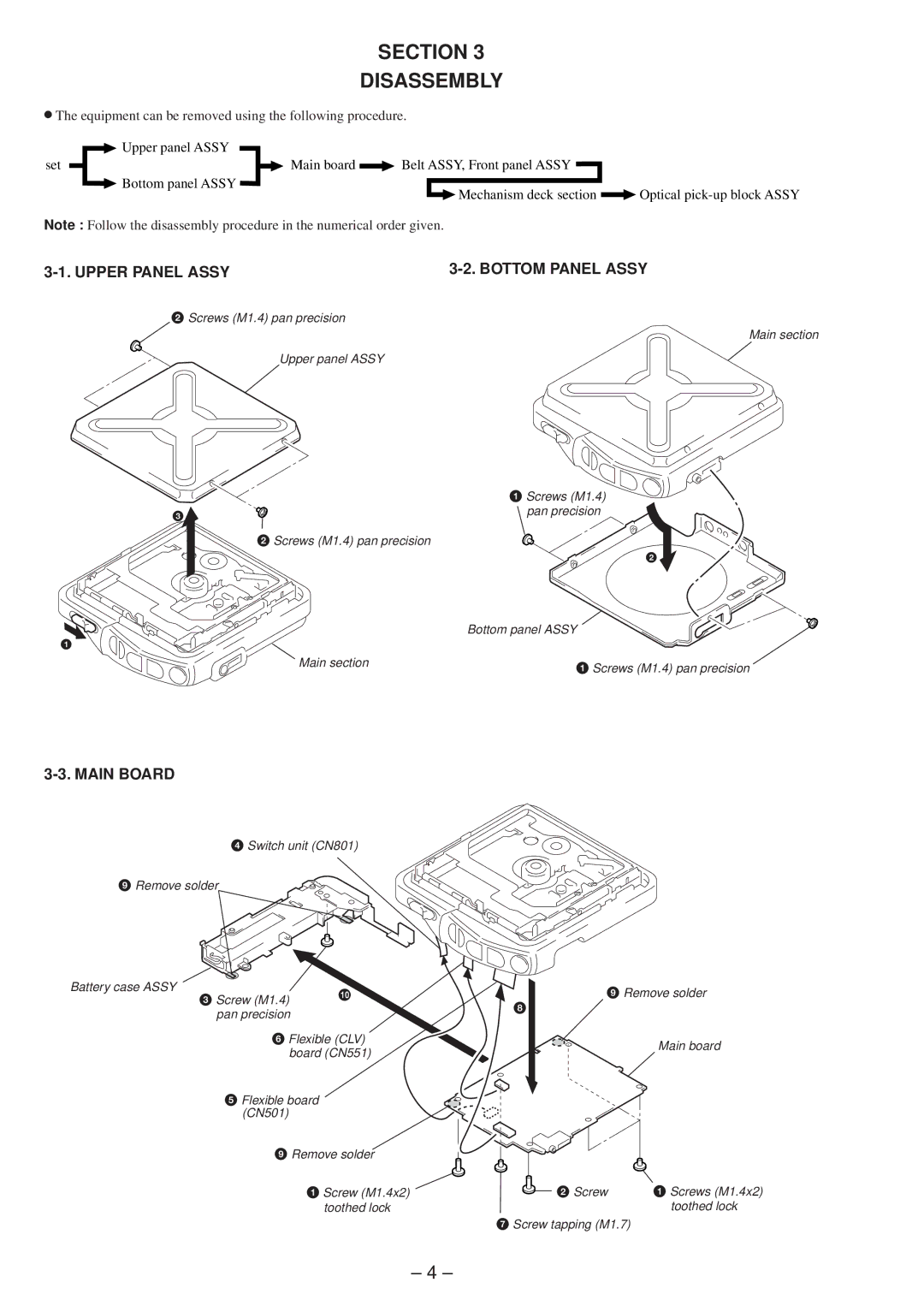
rThe equipment can be removed using the following procedure.
|
| Upper panel ASSY |
|
|
|
| ||
set |
|
|
| Main board |
| Belt ASSY, Front panel ASSY |
|
|
|
|
|
|
| ||||
|
| Bottom panel ASSY |
| Mechanism deck section |
| Optical | ||
|
|
|
|
|
|
| ||
|
|
|
|
|
|
| ||
Note : Follow the disassembly procedure in the numerical order given.
|
|
2Screws (M1.4) pan precision
Main section
Upper panel ASSY
|
| 1 Screws (M1.4) |
3 |
| pan precision |
|
| |
| 2 Screws (M1.4) pan precision |
|
|
| 2 |
|
| Bottom panel ASSY |
1 |
|
|
| Main section | 1 Screws (M1.4) pan precision |
|
|
3-3. MAIN BOARD
4Switch unit (CN801)
9 Remove solder
Battery case ASSY | 3 Screw (M1.4) | !¼ | 9 Remove solder | |
| ||||
|
| 8 |
| |
| pan precision |
|
| |
|
|
|
| |
| 6 Flexible (CLV) |
| Main board | |
| board (CN551) |
| ||
|
|
| ||
| 5 Flexible board |
|
| |
| (CN501) |
|
|
|
| 9 Remove solder |
|
| |
|
| 1 Screw (M1.4x2) | 2 Screw | 1 Screws (M1.4x2) |
|
| toothed lock |
| toothed lock |
|
|
| 7 Screw tapping (M1.7) |
|
– 4 –