SECTION 3
DISASSEMBLY
• This set can be disassembled in the order shown below.
SET  CABINET (REAR), CASSETTE LID
  MAIN BOARD, MECHANISM DECK
  BELT
BELT
Note: Follow the disassembly procedure in the numerical order given.
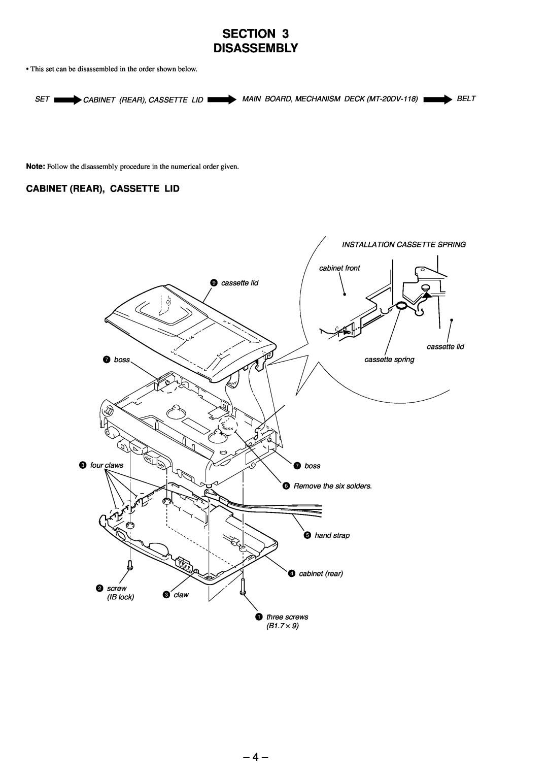
CABINET (REAR), CASSETTE LID
INSTALLATION CASSETTE SPRING
cabinet front
9cassette lid
cassette lid
7 boss | cassette spring |
3 four claws | 7 boss |
6 Remove the six solders.
5 hand strap
4 cabinet (rear)
2 screw | 3 claw | |
(IB lock) | ||
|
1 three screws
(B1.7 ⋅ 9)
– 4 –