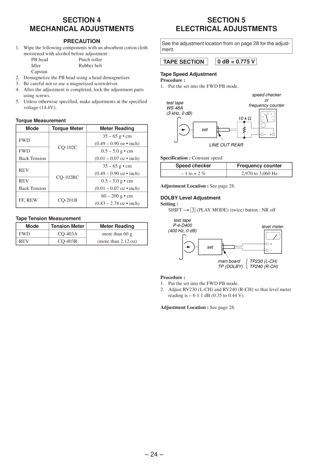
SECTION 4
MECHANICAL ADJUSTMENTS
PRECAUTION
1. Wipe the following components with an absorbent cotton cloth moistened with alcohol before adjustment :
PB head | Pinch roller |
Idler | Rubber belt |
Capstan |
|
2. | Demagnetize the PB head using a head demagnetizer. |
3. | Be careful not to use a magnetized screwdriver. |
4. | After the adjustment is completed, lock the adjustment parts |
| using screws. |
SECTION 5
ELECTRICAL ADJUSTMENTS
See the adjustment location from on page 28 for the adjust- ment.
TAPE SECTION |
| 0 dB = 0.775 V |
Tape Speed Adjustment
Procedure :
1. Put the set into the FWD PB mode.
speed checker
5. Unless otherwise specified, make adjustments at the specified |
test tape
or
voltage (14.4V). |
frequency counter
Torque Measurement
Mode | Torque Meter | Meter Reading | |
|
|
| |
FWD |
| 35 – 65 g • cm | |
| (0.49 – 0.90 oz • inch) | ||
| |||
|
| ||
FWD | 0.5 – 5.0 g • cm | ||
| |||
Back Tension |
| (0.01 – 0.07 oz • inch) | |
|
|
| |
REV |
| 35 – 65 g • cm | |
| (0.49 – 0.90 oz • inch) | ||
| |||
|
| ||
REV | 0.5 – 5.0 g • cm | ||
| |||
Back Tension |
| (0.01 – 0.07 oz • inch) | |
|
|
| |
FF, REW | 60 – 200 g • cm | ||
(0.83 – 2.78 oz • inch) | |||
|
| ||
|
|
| |
Tape Tension Measurement |
| ||
|
|
| |
Mode | Tension Meter | Meter Reading | |
FWD | more than 60 g | ||
|
|
| |
REV | (more than 2.12 oz) | ||
|
|
| |
(3 kHz, 0 dB)
| 10 k ½ |
set |
|
LINE OUT REAR | |
Specification : Constant speed |
|
Speed checker | Frequency counter |
– 1 to + 2 % | 2,970 to 3,060 Hz |
Adjustment Location : See page 28.
DOLBY Level Adjustment
Setting :
SHIFT n 3 (PLAY MODE) (twice) button : NR off
test tape
set
main board | TP230 | |
TP (DOLBY) | TP240 |
Procedure :
1.Put the set into the FWD PB mode.
2.Adjust RV230
Adjustment Location : See page 28.
– 24 –
