IEM3100 / iEM3200 / iEM3300 series
Page
DOCA0005EN-04
Safety information
Important information
Please note
FCC Part 15 notice
Related documents
About the book
Document scope
Validity note
Contents
Chapter Troubleshooting 103
Chapter Specifications
Chapter Power, energy and power factor 105
Chapter Communications via M-Bus
Hazard of Electric SHOCK, EXPLOSION, or ARC Flash
Safety precautions
Safety precautions DOCA0005EN-04
What is in this chapter?
Main characteristics
Chapter Overview
Overview of meter functions
Digital outputs Or overload alarm Pulse output only
5 a meters
Function
IEM31 and iEM33 series
Typical applications
IEM32 series
Typical applications
Overview
Dimensions
Hardware and installation
IEM31 and iEM32 meters
IEM33 meters
Hardware overview
All meters Meter sealing points
IEM3100 / iEM3110 / iEM3115 Direct measurement up to 63 a
Digital input
IEM3200 / iEM3210 / iEM3215 Measurement with CTs
IEM3235 Measurement with CTs and M-Bus communications
IEM3300 / iEM3310 Direct measurement up to 125 a
IEM3275 Measurement with CTs and LonWorks communications
Digital input iEM3355 / iEM3365
Mounting the meter on a DIN rail
DIN rail mounting and dismounting
Dismounting the meter from a DIN rail
Input, output and communications wiring
Pulse output wiring iEM3110 / iEM3210 / iEM3310
Digital input wiring iEM3115 / iEM3215
M-Bus communications connection is polarity-independent
Bus communications wiring iEM3135 / iEM3235 / iEM3335
LonWorks communications wiring iEM3175 / iEM3275 / iEM3375
Power system wiring
Voltage input protection
Current input protection for 1 a and 5 a meters
Fuses and disconnect switch
Direct measurement meter wiring
Power system
IEM
Power system Wiring
Power system Wiring
1 a meter wiring
Single-phase systems with CTs
MA fuses and disconnect switch Shorting block
Three-phase systems with CTs
Three-phase systems with CTs and VTs
Hardware and installation DOCA0005EN-04
1234.5
Front panel display and meter setup
Data display
Data display screen overview
Data display screens
Example navigating the display screens
Data display screens iEM3150 / iEM3250 / iEM3350
Phase 3 Current
Multi Tariff feature
Resets
Resetting accumulated energy using the display
Reset Description
Meter status information
Clock behavior on power interruption
Device clock
Date/time format
Setting the clock initially
Device configuration
Entering configuration mode
Front panel display in configuration mode
Example Configuring a list value
Com. Protection setting
Modifying parameters
Selecting a value from a list
Configuration mode menus
Canceling an entry
Example configuring a numeric value
1PH2W L-L 1PH3W L-L-N
Section Parameter Options Description
Configuration menu for iEM3150 / iEM3350
Com.Protection Contrast Password Reset Config
By Internal Clock
Configuration menus for iEM3200 / iEM3210 / iEM3215
Configuration menus for iEM3250
Com.Protection
3PH3W 3PH4W
Section Parameter Options Description
Front panel display and meter setup DOCA0005EN-04
Communications LED indicator for Modbus devices
Modbus communications settings
Communications via Modbus RS-485
Modbus communication overview
Function list
Modbus functions
Table format
Unit table
Command interface overview
Command interface
Command request
Command result
Command Action Size Type Unit Range Description
Command list
Set Date/Time
Action Size Type Unit Range Description Number
Set Pulse Output iEM3155 / iEM3255 / iEM3355
Set Tariff iEM3155 / iEM3255 / iEM3355
Size Type Unit Range Description
Input Metering Setup iEM3155 / iEM3255 / iEM3355
Overload Alarm Setup iEM3155 / iEM3255 / iEM3355
Communications Setup
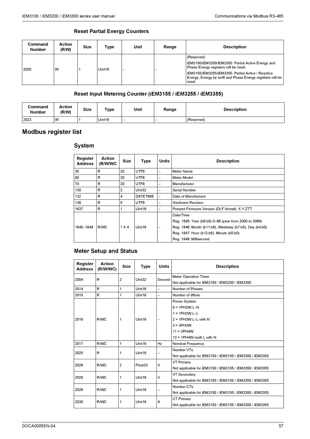
Reset Partial Energy Counters
Meter Setup and Status
Reset Input Metering Counter iEM3155 / iEM3255 / iEM3355
Modbus register list
Command Interface
Energy Pulse Output Setup iEM3155 / iEM3255 / iEM3355
Input Metering Setup iEM3155 / iEM3255 / iEM3355
Communication
Digital Input iEM3155 / iEM3255 / iEM3355
Current, voltage, power, power factor and frequency
Digital Output iEM3155 / iEM3255 / iEM3355
Meter Data
Energy, energy by tariff and input metering
Overload Alarm iEM3155 / iEM3255 / iEM3355
Read Device Identification
Energy values 32-bit floating point
Object ID Name/Description Length Value
Communications via LonWorks
LED indicators for LonWorks meters
LonWorks communications overview
LonWorks communication implementation
General variables
Location of the service pin and Neuron ID
System variables
Green communications LED
Type Description
Energy and energy by tariff measurements
Instantaneous RMS measurements
Digital input configuration and status information
System configuration information
Alarm status
Meter status information
Resets
Meter configuration properties
Date/time setup
Network variable label Type Description Action
Digital input setup
Basic setup
Input metering setup
Struct Members Range / options Description
Multi Tariff setup
Overload alarm setup
Network propagation rate setup
Range / options Description
Installing and registering the LonMaker plug-in
LonMaker plug-in interface
Browsing the meter using the LonMaker plug-in
Plug-in has the following tabs
Tab name Description
Meter Status
Communications via LonWorks DOCA0005EN-04
Communications via M-Bus
Configuring basic communications settings
Bus communications overview
Key terms
Bus protocol implementation
Bus protocol support
Variable data structure telegram information
Fixed data header
Data record header information
Description Bin Hex
Manufacturer-specific Vife codes
Meter information
Telegram information for data records
Bin Hex
Primary VIF Primary Vife
Date and time information
Instantaneous measurements
Data format
Data format Primary VIF
Power system configuration information
Digital input and output status information
Data format Primary Vife
Alarm status information
Telegram information for meter configuration
Supported Vife codes for meter configuration
Action Description Bin Hex
Power system setup
Date/time setup
Multi Tariff setup
Data format Primary VIF Description
Digital output setup
Digital input setup
Overload alarm setup and acknowledgment
Baud rate
Installing the M-Bus tool
Bus tool for data display and meter configuration
Accessing the meter using the tool
Resets
Viewing meter data using the M-Bus tool
Configuring the meter using the M-Bus tool
Select Setup Config to switch to configuration mode
Section Description
Communications via M-Bus DOCA0005EN-04
BACnet communications overview
Communications via BACnet
BACnet protocol support
Related topics
BACnet communications implementation
Configuring basic communication parameters
Following standard object types are supported
Object type
BACnet object and property information
Communications LED indicator for BACnet meters
Change of Value COV subscriptions
Device object
Object ID Units Default COV Object name / description
Analog Input objects
Energy and energy by tariff measurements
Meter information
Instantaneous RMS measurements
Digital input and output setting information
Communications settings information
Analog Value object
Command
Binary Input objects
Object ID Object name / description
Communications via BACnet DOCA0005EN-04
Electrical characteristics
Chapter Specifications
Power system inputs iEM31 meters
Power system inputs iEM33 meters
Power system inputs iEM32 meters
Characteristic Value Meters
Inputs and outputs
Mechanical characteristics
Environmental characteristics
Measurement accuracy
Internal clock
Modbus communications
LonWorks communications
BACnet communications
Bus communications
Specifications 102 DOCA0005EN-04
Do not open the meter. Opening the meter voids the warranty
Troubleshooting
Diagnosis screen lists any current diagnostic codes
Diagnosis screen
Description Possible solution
Diagnostic codes
Power PQS
Power, energy and power factor
Power and the PQ coordinate system
Power flow
True PF and displacement PF
Power factor PF
Energy delivered imported / energy received exported
PF lead / lag convention
PF sign convention
Power and PF lead / lag
PF lead / lag summary
PF sign in IEC
To +1
Power factor register format
Quadrant
To +1 +1 to +2
PF formula
Quadrant PF range
Power, energy and power factor 110 DOCA0005EN-04
Page
Schneider Electric 35, rue Joseph Monier CS30323