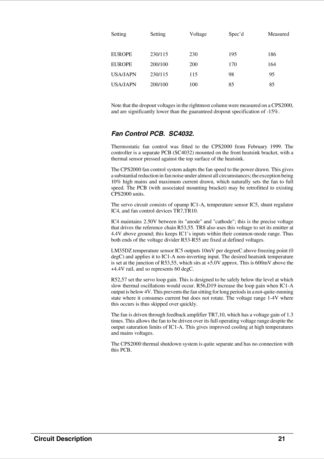
Setting | Setting | Voltage | Spec’d | Measured |
EUROPE | 230/115 | 230 | 195 | 186 |
EUROPE | 200/100 | 200 | 170 | 164 |
USA/JAPN | 230/115 | 115 | 98 | 95 |
USA/JAPN | 200/100 | 100 | 85 | 85 |
Note that the dropout voltages in the rightmost column were measured on a CPS2000, and are significantly lower than the guaranteed dropout specification of
Fan Control PCB. SC4032.
Thermostatic fan control was fitted to the CPS2000 from February 1999. The controller is a separate PCB (SC4032) mounted on the front heatsink bracket, with a thermal sensor pressed against the top surface of the heatsink.
The CPS2000 fan control system adapts the fan speed to the power drawn. This gives a substantial reduction in fan noise under almost all circumstances; the exception being 10% high mains and maximum current drawn, which naturally sets the fan to full speed. The PCB (with associated mounting bracket) may be retrofitted to existing CPS2000 units.
The servo circuit consists of opamp
IC4 maintains 2.50V between its "anode" and "cathode"; this is the precise voltage that drives the reference chain R53,55. TR8 also uses this voltage to set its emitter at 4.4V above ground; this keeps IC1’s inputs within their
LM35DZ temperature sensor IC5 outputs 10mV per degreeC above freezing point (0 degC) and applies it to
R52,57 set the servo loop gain. This is designed to be safely below the level at which slow thermal oscillations would occur. R56,D19 increase the loop gain when
The fan is driven through feedback amplifier TR7,10, which has a voltage gain of 1.3 times. This allows the fan to be driven over its full operating voltage range despite the output saturation limits of
The CPS2000 thermal shutdown system is quite separate and has no connection with this PCB.
Circuit Description | 21 |