( INSTALLATION STEP 4)
LEVEL SEmlNG
The input levels are adjusted by means of the input level controls located on the front of the amplifier. This is a unique
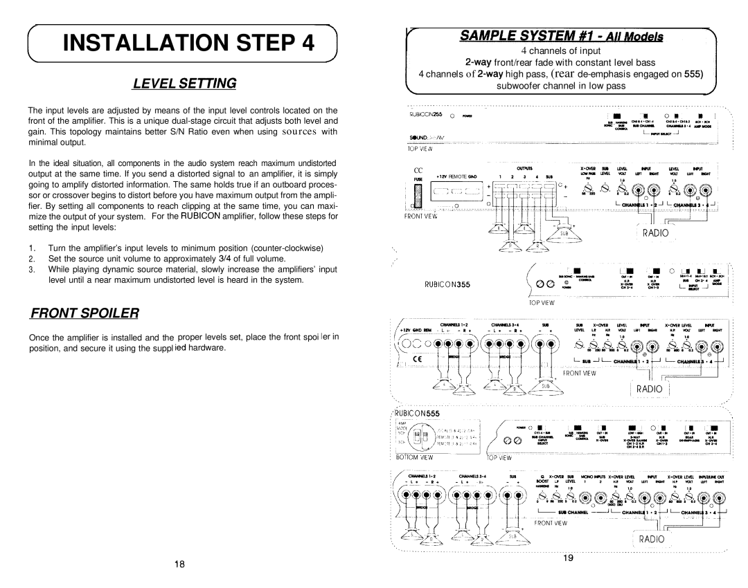
4 channels of input
4 channels of
subwoofer channel in low pass
| |||||||
_ | _. | . |
| _ |
|
| |
RUBiCGfu255 | 0 - | cm | 0 | m | ] | ! | |
|
|
| cnse4*cx14 | cH2~4.atI~2 |
|
|
|
|
|
| SLN- | cnAnmu2*4 |
|
|
|
In the ideal situation, all components in the audio system reach maximum undistorted output at the same time. If you send a distorted signal to an amplifier, it is simply going to amplify distorted information. The same holds true if an outboard proces- sor or crossover begins to distort before you have maximum output from the ampli- fier. By setting all components to reach clipping at the same time, you can maxi- mize the output of your system. For the RUBICON amplifier, follow these steps for setting the input levels:
1.Turn the amplifier’s input levels to minimum position
2.Set the source unit volume to approximately 3/4 of full volume.
3.While playing dynamic source material, slowly increase the amplifiers’ input level until a near maximum undistorted level is heard in the system.
FRONT SPOILER
CC
FUSE
, \ \
,, I I
tl2V REMOTE GND
Once the amplifier is installed and the proper levels set, place the front spoi Ier in position, and secure it using the suppl ied hardware.
+12VWDREM - L +
CHANNELS394
L*