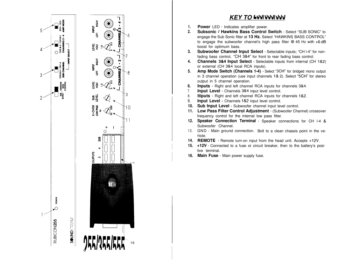
KEY TO CALLOUTS
1.Power LED - Indicates amplifier power.
2.Subsonic / Hawkins Bass Control Switch - Select “SUB SONIC” to engage the Sub Sonic filter at 13 Hz. Select “HAWKINS BASS CONTROL” to engage the subwoofer channel’s high pass filter @I 45 Hz with +6 dB boost for optimum bass.
3.Subwoofer Channel Input Select - Selectable inputs; “CH
4.Channels 3&4 Input Select - Selectable inputs from internal (CH l&2) or external (CH 38~4 local RCA inputs).
5.Amp Mode Switch (Channels
6.Inputs - Right and left channel RCA inputs for channels 3&4.
7.Input Level - Channels 3&4 input level control.
8.ltiputs - Right and left channel RCA inputs for channels l&2.
9.Input Level - Channels l&2 input level control.
10.Sub Input Level - Subwoofer channel input level control.
11.Low Pass Filter Control Adjustment - (Subwoofer Channel) crossover frequency control for the internal low pass filter.
12.Speaker Connection Terminal - Speaker connections for CH
13.GND - Main ground connection. Bolt to a clean chassis point in the ve- hicle.
14.REMOTE - Remote
15.+12V - Connected to a fuse or circuit breaker, then to the battery’s posi- tive terminal.
16.Main Fuse - Main power supply fuse.
‘. ‘. 1 6